
ALL MATERIAL COPYRIGHT KEVIN SCOTT 2011. LINKS TO THIS SITE ARE WELCOME BUT DO NOT COPY MATERIAL FROM THIS SITE TO ANY OTHER WEBPAGE.


If you find this site useful, please support it by making a donation of $1 to help maintain and develop it. Click on the PAYPAL DONATE button to do this safely. But there is no obligation - please avail yourself of the information and facilities of the site at no charge.
This paper describes a method for controlling the speed of a stepper motor to a resolution of 1 part in 60,000. The normal way of speed variation of a stepper motor is to generate a high clock frequency and then to divide that frequency with a programmable divider to supply the clock pin of a stepper motor controller IC. The resolution of such a system depends upon the source frequency and the value of the frequency divisor. Clearly the higher the source frequency, the larger the divisor for a given motor speed, so the available resolution of the speed can improve with ever increasing source frequencies. Unfortunately the availability of frequency dividers diminishing with rising frequency and the circuit complexities increase with the use of frequencies beyond 100 MHz.
So, for example, using a 200 step motor, a 32MHz source frequency, to obtain a rotational speed of 1500 rpm, a divisor is required of 6400. This limits the resolution of the speed control to 1 in 6400. If the motor speed is required to be set and controlled to a greater precision than this, without an increase in the source clock speed, a further fine control needs to be introduced.
The approach investigated here is to use a programmed voltage applied to a varicap diode to make small adjustments to the source clock frequency to provide a further order of magnitude of adjustment. With a divisor of 6400, the fine adjustment would have to provide a maximum range of 1/6400, or 156ppm. As will be seen, with the components specified, the range of this fine adjustment is 20 ppm/volt across a span of 10 volts. This is sufficient to give an overall control resolution of 1 in 64000 for a 1500 rpm motor, and if a 50MHz crystal were used, the same resolution can be obtained for a motor running at 3000 rpm.
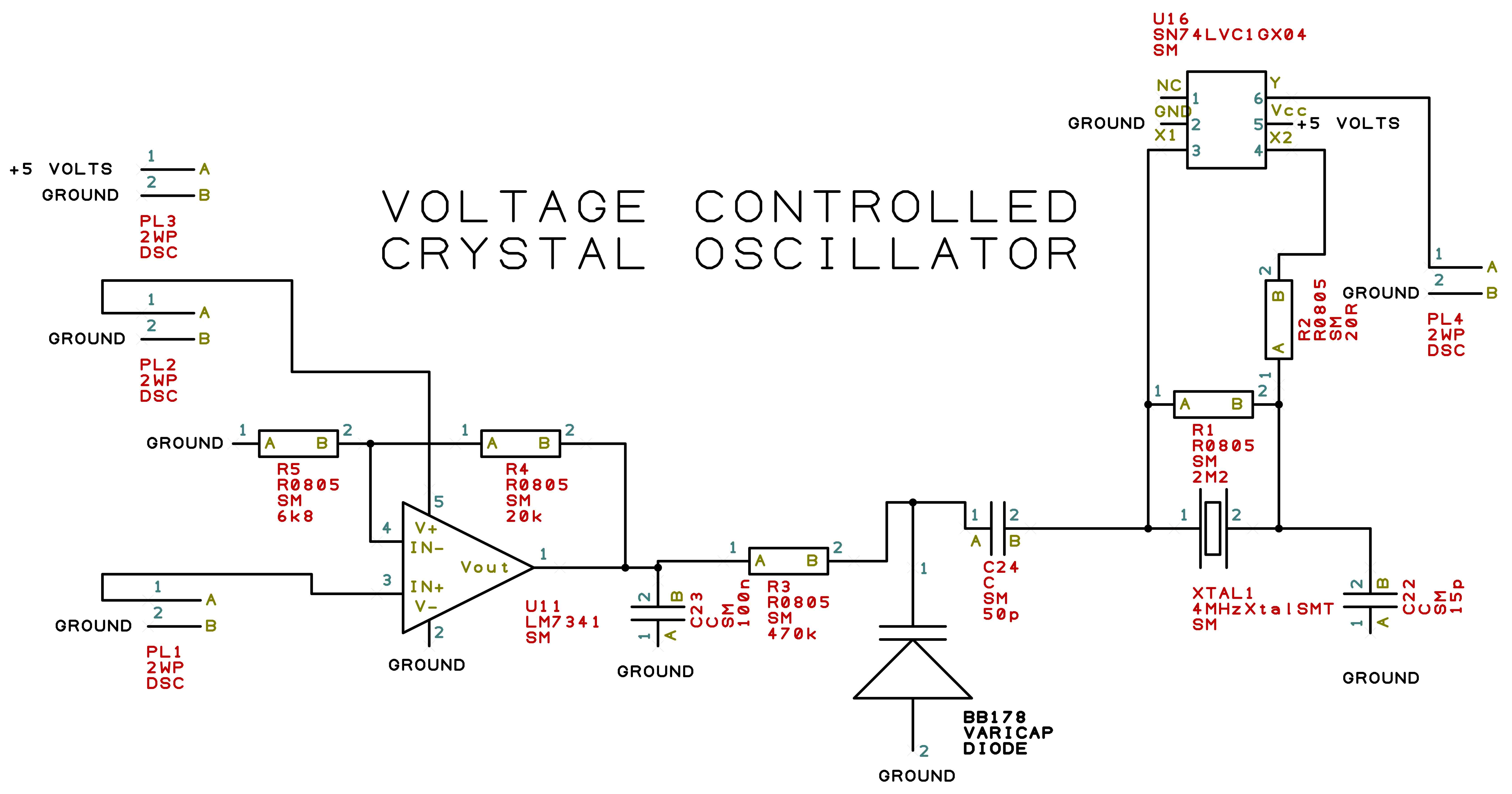
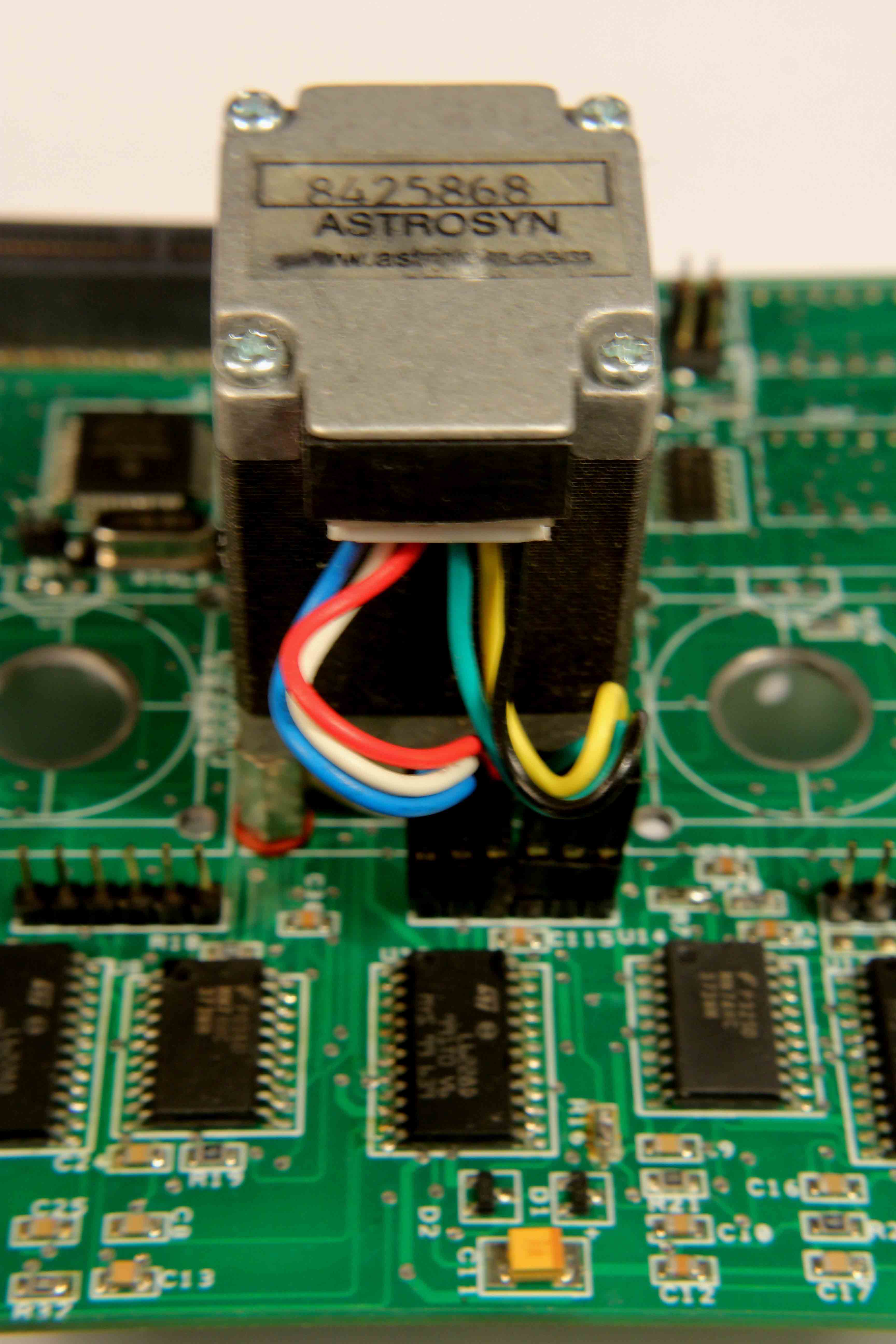
The circuit of the voltage controlled crystal oscillator is shown to the right. U11 is an amplifier with a set gain of 4 which allows a control voltage of 0-5 volts from a digital to analogue converter to appear as 0-20 Volts applied to the varicap diode (Farnell 175-7782). The varicap diode constitutes the loading capacitor for the crystal which is held in oscillation by the oscillator driver U16.
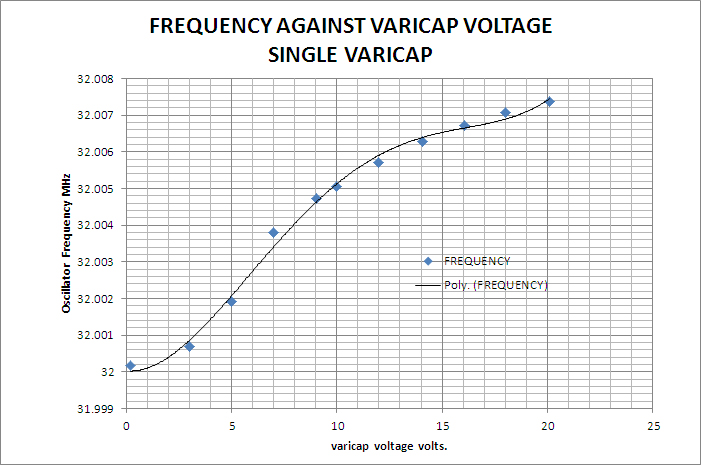
The frequency of oscillation was measured using an Apollo 100 Counter Timer while the varicap diode was loaded with various voltages. The results are shown in the table.
| Vvaricap | FREQUENCY |
| volts | MHz |
| 0.21 | 32.000168 |
| 3 | 32.000693 |
| 3 | 32.000685 |
| 5 | 32.001921 |
| 5 | 32.001914 |
| 7 | 32.003811 |
| 7 | 32.00381 |
| 9.04 | 32.004722 |
| 9.04 | 32.004719 |
| 10.01 | 32.005066 |
| 10.01 | 32.005067 |
| 12 | 32.005706 |
| 12 | 32.00571 |
| 14.06 | 32.006281 |
| 14.06 | 32.006281 |
| 16.06 | 32.006716 |
| 16.06 | 32.006723 |
| 18.03 | 32.00707 |
| 18.03 | 32.007071 |
| 20.1 | 32.007361 |
| 20.1 | 32.007362 |
The plot of oscillator frequency against varicap voltage is shown with the linear part of the curve having a slope of 670 Hz per volt or about 20ppm/volt.
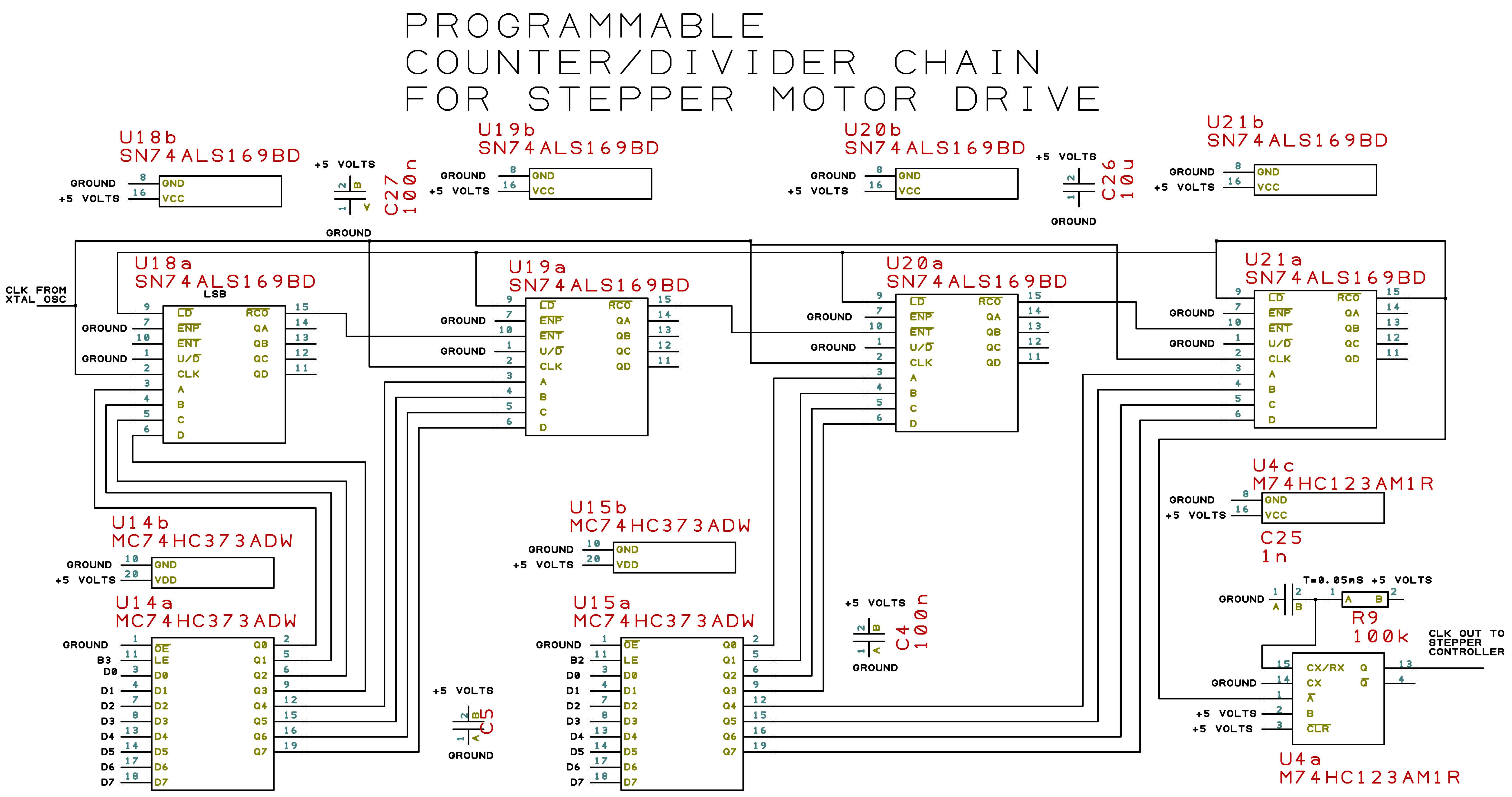
The circuit of the divider chain is shown in the accompanying schematic. U18, U19, U20 & U21 are each 4 bit programmable down counters which are loaded from two bidirectional latches which are themselves loaded from a a microcontroller. The counter train reduces the frequency of the clock by the divisor loaded into them and the output pulse shaped by the monostable U4 and thence applied to the stepper motor controller clock input.
The extra fine control is generated from the microcontroller by supplying data to a digital to analog converter to generate the varicap voltage. Thus a combination of the DAC data and the divisor digits provides an overall resolution of 1 part in 60,000.
| Definitions | ||
| Quantity | Units | symbol |
| base crystal frequency | MHz | f0 |
| divisor | M | |
| motor steps/rev | n | |
| Motor period | μsec | TR |
| varicap slope | MHz/volt | α |
| Max varicap voltage | volts | Vmax |
| Varicap voltage | volts | V |
The Divisor M is given by: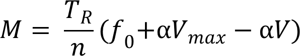
The first step is to carry out an integer calculation: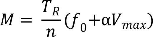 and obtain an integer value of M which will be fed to the divisor registers. The remainder then has to be processed to calculate a value for the varicap voltage. We take the basic equation.
 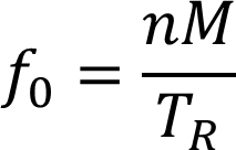 and differentiate:
 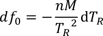 . Putting the remainder from the integer division equal to dTR, we obtain,
 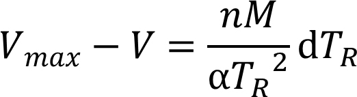 .
.
This provides us with the value of the varicap voltage required to adjust the base oscillator frequency to the correct value for 5 digit precision on the rotational period of the motor.