
ALL MATERIAL COPYRIGHT KEVIN SCOTT 2011. LINKS TO THIS SITE ARE WELCOME BUT DO NOT COPY MATERIAL FROM THIS SITE TO ANY OTHER WEBPAGE.


If you find this site useful, please support it by making a donation of $1 to help maintain and develop it. Click on the PAYPAL DONATE button to do this safely. But there is no obligation - please avail yourself of the information and facilities of the site at no charge.
It becomes necessary from time to time to calibrate a gas chromatographic detector or other sensor, perhaps across several orders of magnitude, which using individual samples or sample mixtures can be a lengthy and tedious task. The device described here provides a convenient means of calibrating a detector across its full dynamic range in a single experiment involving one sample injection only.
The Logarithmic Dilution Vessel consists of an enclosed chamber which is stirred continuously by a rotating vane which is arranged in such a way to avoid, as far as possible, any unstirred volumes existing within the chamber. An inlet and an outlet are provided at opposite points across the chamber and a current of carrier gas caused to flow through it. A suitable injection port is fitted to the inlet to enable a measured quantity to be introduced of the substance for which a calibration is required.
The mixing vane, preferably made of PTFE, is mounted upon a shaft fitted with turned bearings and usually caused to rotate by means of a ferromagnetic rod mounted at right angles to the axis of rotation. The vane assembly can then be conveniently rotated by means of a laboratory magnetic stirrer.
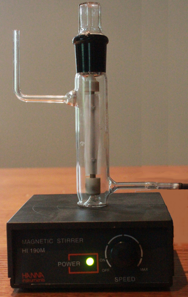
A particular realisation of the device is shown in the photograph and diagrammatically below.
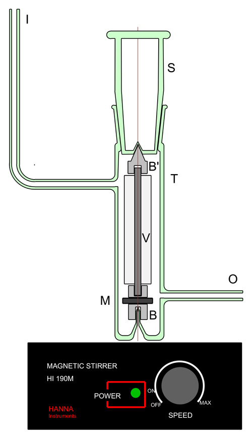
The diagram shows a practical realisation of a Logarithmic Dilution Vessel of suitable proportions to calibrate chromatographic and other detectors used for analytical purposes. A B24/29 borosilicate socket T is closed at the lower end and a glass conical protuberance formed in the flattened end projecting upwards into the glass reservoir. Two side-arms, I and O are provided to allow inlet and outlet of the gas flow respectively. The quickfit socket is closed by a glass stopper S, the lower end of which is provided with a conical indentation in the glass surface to accommodate the upper PTFE bearing B'. The stirrer consists of a stainless steel shaft upon which is mounted a PTFE vane V with PTFE bearings B & B' machined to match the pivots fashioned in the glass at each end. A soft iron rod M, 3mm in diameter is fitted to the lower PTFE bearing to enable the shaft to be rotated by an external magnetic stirrer. When the device has been assembled to verify the free-running of the shaft, the ground glass joint is sealed with Black Wax (Apiezon W).
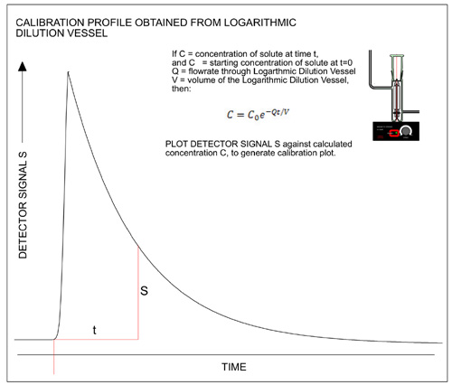
The theory of the Logarithmic Dilution Vessel is straightforward. If the volume of the vessel is V ml, and the flowrate Q ml/min, the concentration of solute is C at time t minutes and C0 at t =0, then
in time dT, the change in concentration at the outlet, dC = -CQdt/V.
Integrating,

If the Logarithmic Dilution Vessel is placed in series with the detector of which a calibration is required, and a known quantity of the calibration substance in injected into the inlet I, the detector output profile obtained will appear in form similar to the profile shown on the left. If the signal values S1, S2, S3... obtained at various measured times t1, t2, t3... are plotted against values of C calculated from the equation above, a calibration plot can be readily generated.
1. The gas flowrate Q, must be constant throughout the calibration process and measured carefully. A bubble flowmeter can be used conveniently for this purpose.
2. The volume V, of the Logarithmic Dilution Vessel must also be measured accurately and probably the best way of doing this is gravimetrically, by weighing the Vessel and then filling it with water and re-weighing.
3. Although not shown in the sketch above, the Logarithmic Dilution Vessel can be used to calibrate a detector over a large number of orders of magnitude.