
ALL MATERIAL COPYRIGHT KEVIN SCOTT 2011. LINKS TO THIS SITE ARE WELCOME BUT DO NOT COPY MATERIAL FROM THIS SITE TO ANY OTHER WEBPAGE.


If you find this site useful, please support it by making a donation of $1 to help maintain and develop it. Click on the PAYPAL DONATE button to do this safely. But there is no obligation - please avail yourself of the information and facilities of the site at no charge.
Very early in the Eighteenth Century a Mr Caswell FRS of Oxford wrote to The Reverend Mr Flamsteed MRSS describing a "new baroscope" which had extraordinary sensitivity to very small pressure changes. It was based upon a principle illustrated in figure 1. Figure 1a represents a hydrometer used for determining the density of liquids. According to Archimedes' Principle, the hydrometer sinks to a point where it displaces its own weight of liquid. Thus in liquids of low density it sinks to a lower point than liquids of higher density. A calibrated stem provides a direct measure of the liquid density.
Figure 1b shows a modified hydrometer in which a small hole is blown at the lower end of bulb B, thus admitting a certain amount of the liquid which compresses the air in B to a small degree. In a liquid of known constant density, the modified hydrometer will float at a point where the weight of liquid it displaces is equal to its own weight. If the atmospheric pressure increases, the gas captured in B is compressed and this displaces a smaller volume of liquid. The modified hydrometer therefore sinks to a new position of hydrostatic equilibrium. If the stem is suitably calibrated, and the liquid maintained at a constant temperature, the instrument can be used as a barometer.
Two hundred years after Mr Caswell wrote his letter, a carefully thermostated version of the same instrument was designed and constructed by Karl Fischer, for the purposes of altitude measurement in hot air balloons.(see Figure 2) Fischer recognised that the readings given by the instrument were independent of the gravitational acceleration and so measurements would be unaffected by vertical accelerations or decelerations of the balloon.
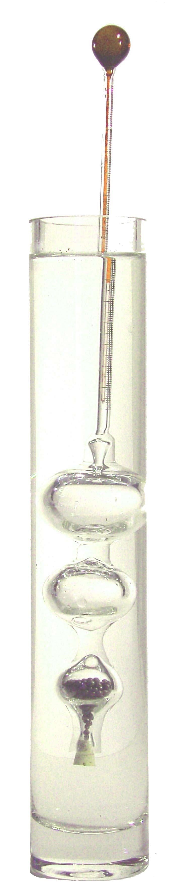
These two published designs and a further design published by William Brand in 1839 made no attempt to provide temperature compensation- rather they were operated in isothermal conditions. The version of the instrument described here is supplied with temperature compensation for which an application for a patent has been made. Consider the Hydrostatic Barometer depicted diagrammatically in Figure 3. It is provided with three bulbs. Bulb A is completely sealed and is provided for buoyancy. Bulb C and its contents of lead shot act as a counter weight. Bulb B, which has a small aperture blown in it at D is the barometric bulb into which water partly enters when the instrument is in use. The relative sizes of bulbs A, B & C, the weight of lead shot, diameter and weight of the stem S can all be calculated such that an increase of atomspheric pressure of 1 mB causes the instrument to sink by 1 mm and vice versa.
Inevitably the instrument exhibits a large temperature coefficient which previous authors have overcome by thermostatting their instruments. In the instrument depicted in Figure 3, with a sensitivity to the barometric pressure of 1mm/mB, the temperature coefficient was calculated to be -3.83mm/degree C. The minus sign signifies that the barometer rises in the water when the temperaturee increases. The thermometer T in Figure 3 was constructed to exhibit a rate of 3.83mm/deg C and its insertion with the bulb uppermost in stem S, results in an instrument fully compensated for temperature and readily readable in mB. A scale graduated in mm was engraved on the stem S. The amount of air in the barometric bulb B could be adjusted by allowing the cork below bulb C to come into contact with the bottom of the vessel in which the instrument was floating. If this was done with very moderate force, a bubble of air could be forced from B resulting in the instrument floating a little lower in the water. Repetition of this procedure allowed the instrument be adjusted to float at the correct level.
This correct level was determined as follows: First, a reference pressure was chosen, conveniently 1000mB, at which the instrument would float with the end of the thermometer thread exactly level with the meniscus of the water against the stem S. At this constant pressure, this condition will prevail at all temperatures in the compensation range. If the pressure increased to n mB above 1000, the instrument would descend to a point such that the thermometer thread stood below the water level by n mm. Similarly should the atmospheric pressure fall n mB below 1000 mB, the thread would stand above the water level by n mm. Setting the instrument involved knowing the prevailing atmospheric pressure at the time and adjusting the level at which the instrument floated according to the principle outlined above.
Referring again to Figure 1b, if the radius of bulb
B is![]() , and its total volume is
, and its total volume is ![]() , then the volume of gas is
, then the volume of gas is
![]()
If the atmospheric pressure is ![]() , and the density of
the liquid is
, and the density of
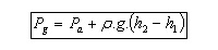
the liquid is![]() and the gravitational acceleration g, the pressure in the bulb
B will be given by
and the gravitational acceleration g, the pressure in the bulb
B will be given by
Applying Archimedes Principle:

Where V is the total immersed volume of the barometer
and ![]() is the total volume of tubing:
is the total volume of tubing: ![]()
At an absolute temperature T, the volume of gas
is ![]() and thus,
and thus,
![]()
Rearranging these equations for h1, and, for convenience, defining
![]() and
and ![]() and
and ![]() ,
yields a quadratic equation,
,
yields a quadratic equation,
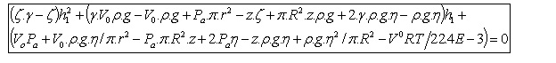 This
rather unwieldy equation can easily be solved numerically to give a value of
This
rather unwieldy equation can easily be solved numerically to give a value of ![]() which
is the sensitivity of the instrument and for
which
is the sensitivity of the instrument and for ![]() ,
which is the temperature coefficient.
,
which is the temperature coefficient.
By adjusting the physical dimensions of the instrument, the sensitivity can be set at any convenient value and in the case of the instrument described here, the sensitivity was set at 1mm per millibar, ( I.e. a little more sensitive than a standard mercury barometer.)
While the adjustment of the dimensions of the hydrostatic barometer determines its sensitivity and temperature coefficient, other considerations must be made to guarantee its hydrostatic stability. The instrument will float securely in a vertical position if the sum of the moments which tend to sustain it vertically is greater than the moments which tend to force it horizontal. The former is the sum of the weights below the surface times their respective distances from the surface. The moments tending to force the instrument horizontal are of two sorts: (i) the weights above the surface times their distances from it, and (ii) the Archimedian upthrusts below the surface times their distances to the surface.
Using the dimensions of figure 4, an equation was derived for this total moment
and dimensions adjusted so that the instrument would be stable under all conditions
of use. Figure 5 shows the dimensions of the instrument which were found
to give hydrostatic stability.
The instrument was constructed from 11mm OD x 4mm ID borosilicate tubing using a programmable glass-working machine. Figure 6 shows the sequence of operations to produce the required 3 bulbs in the desired configuration.
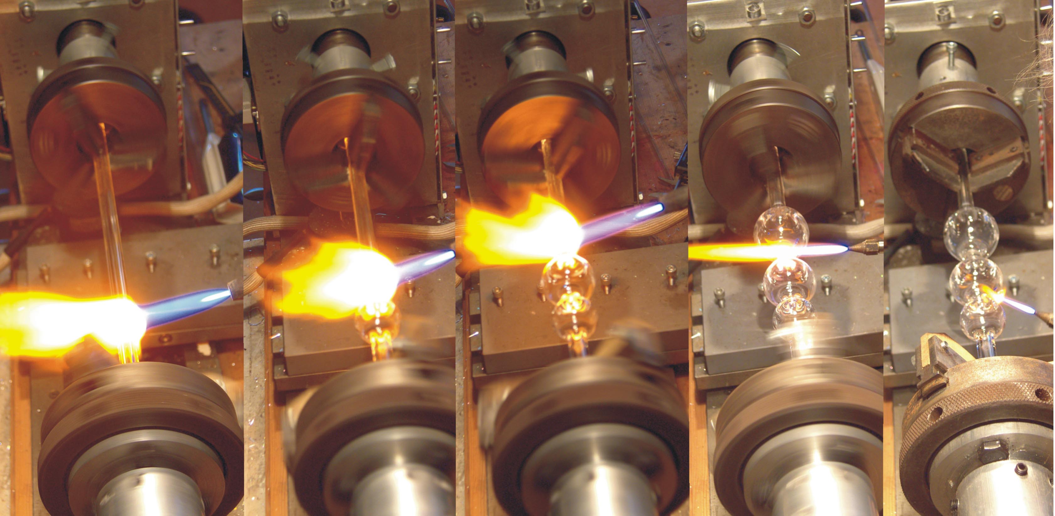
Figure 6. The construction of the TTS007 Hydrostatic Barometer. From left to right: (i) blowing the counterweight bulb to 24mm diam, (ii)blowing the barometric bulb for which the requirement of precision is greatest to 33mm, (iii) The buoyancy bulb is blown to 38mm and up to 42mm is acceptable. (iv) After the bulbs have been blown the stem between the buoyancy bulb and the barometric bulb is sealed.(v) The aperture in the barometric bulb is opened and then the stem below it sealed.
After blowing the bulbs and sealing between them, the required aperture was opened in the lower section of the barometric bulb, and the tubulure fashioned to take the cork. A graduated tube was attached to the upper end and the whole annealed overnight. A thermometer was fashioned by blowing a bulb 18mm in diameter and sealing it to a 1mm ID x1.6mm OD capillary tube which had been previously internally silanised using hexamethyl disilazane ( 10% in heptane, 95C, 6 hours). The finished thermometer was filled with dry Toluene dyed with Solvent Red TAX.
Sufficient lead shot was placed in the lower bulb to enable the instrument to float at somewhat above the correct height. Gentle contact between the cork and the bottom of the containing vessel enabled the discharge of sufficient air from the barometric bulb to bring the instrument to the correct level corresponding to the prevailing atmospheric pressure. Figure 7 shows the completed instrument.
The performance of the hydrostatic barometer was estimated by taking readings daily from two prototypes, and comparing them with readings from a Precision Laboratory Sympiesometer over a 26-day period. The results are plotted in figure 8.
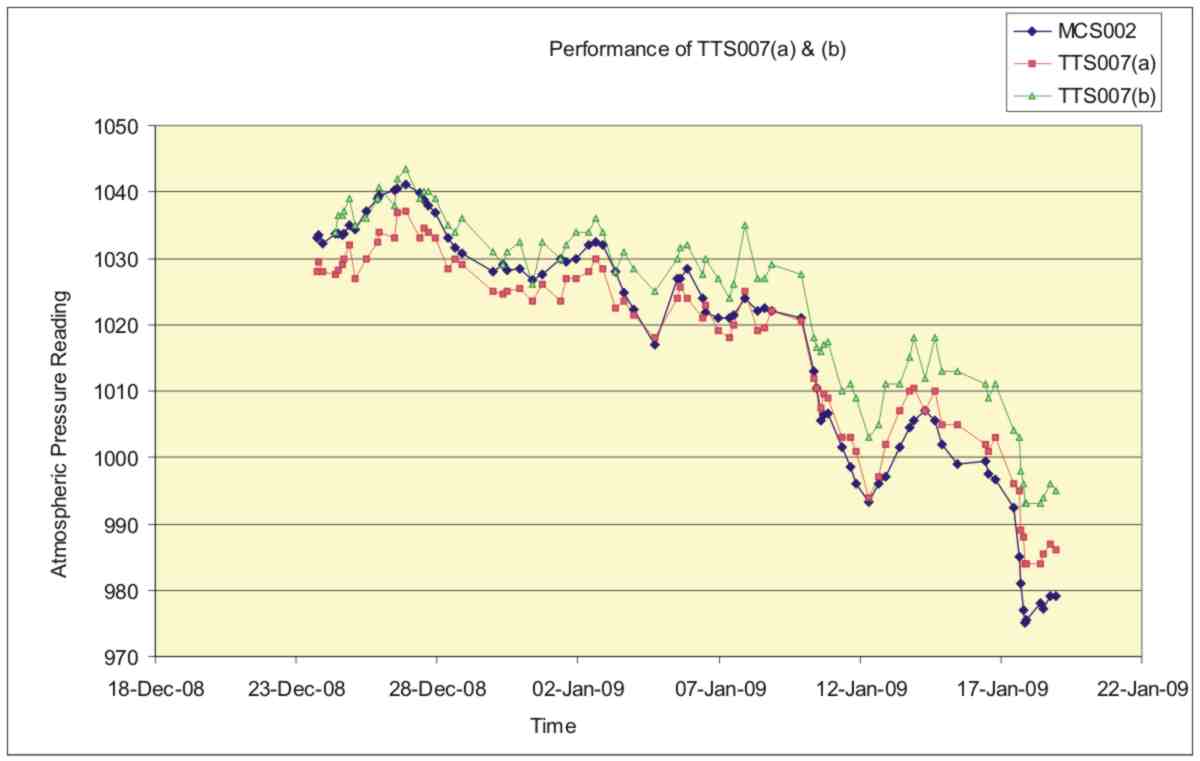
Figure 8. A comparison between the readings obtained from two hydrostatic barometers TTS007a & TTS007b with those from a Meteormetrics Precision Sympiesometer MCS002.
The plots, which cover a range of pressures from 975mB to 1040mB, show a close correlation with the measured standard. There is an offset of about 5mB between TTS007b and the standard which is derived from an error in setting the instrument at the start. Careful examination of the plots shows that the response of the two hydrostatic barometers was slightly lower than that predicted from the design and this was probably due to the barometric bulb filling to a greater extent with water than was envisaged. Figure 9 shows a plot of the response of the two prototypes plotted against atmospheric pressure and reveals this lower than predicted response more clearly.
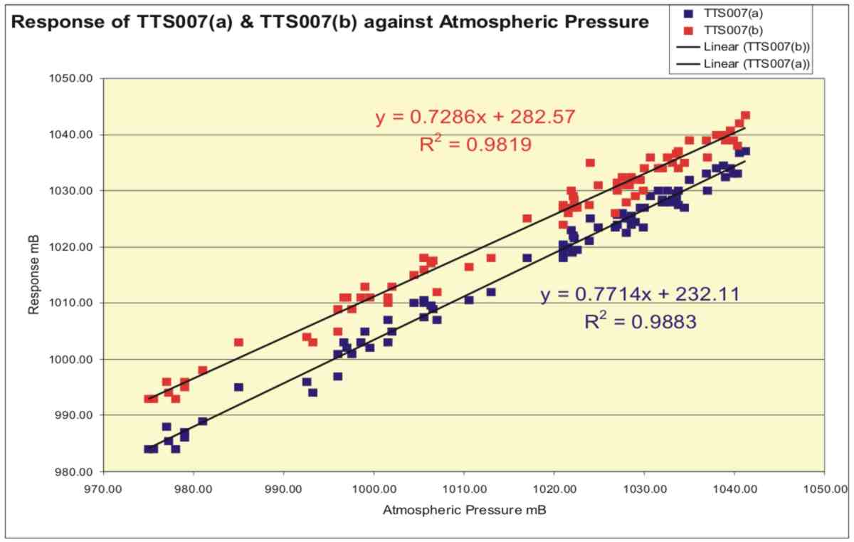
Figure 9. Plots of readings obtained from the hydrostatic barometer prototypes against atmospheric pressure with linear trendlines.
Least squares regression shows the response of the two instruments to be 0.73 and 0.77 mm/mB, i.e. a little less than the intended 1.0mm/mB. This can be corrected by about a 6% increase in the diameter of the Barometric Bulb on future instruments.
Figure 10 shows these corrected values of response plotted against atmospheric pressure. The standard deviation of these points was calculated as 2.1 mB which can be taken as a measure of the precision of the instruments.
The instruments displayed a repeatability and precision beyond that which might be expected from a blown glass item floating in water. They would certainly be satisfactory for general observation of the weather and basic forecasting. Their great advantage is their transparency - not only that they can be easily observed and read, but their mode of operation is clear from reasoned observation. Their operation depends upon a good deal of elementary physics and so they offer considerable scope in the field of education.
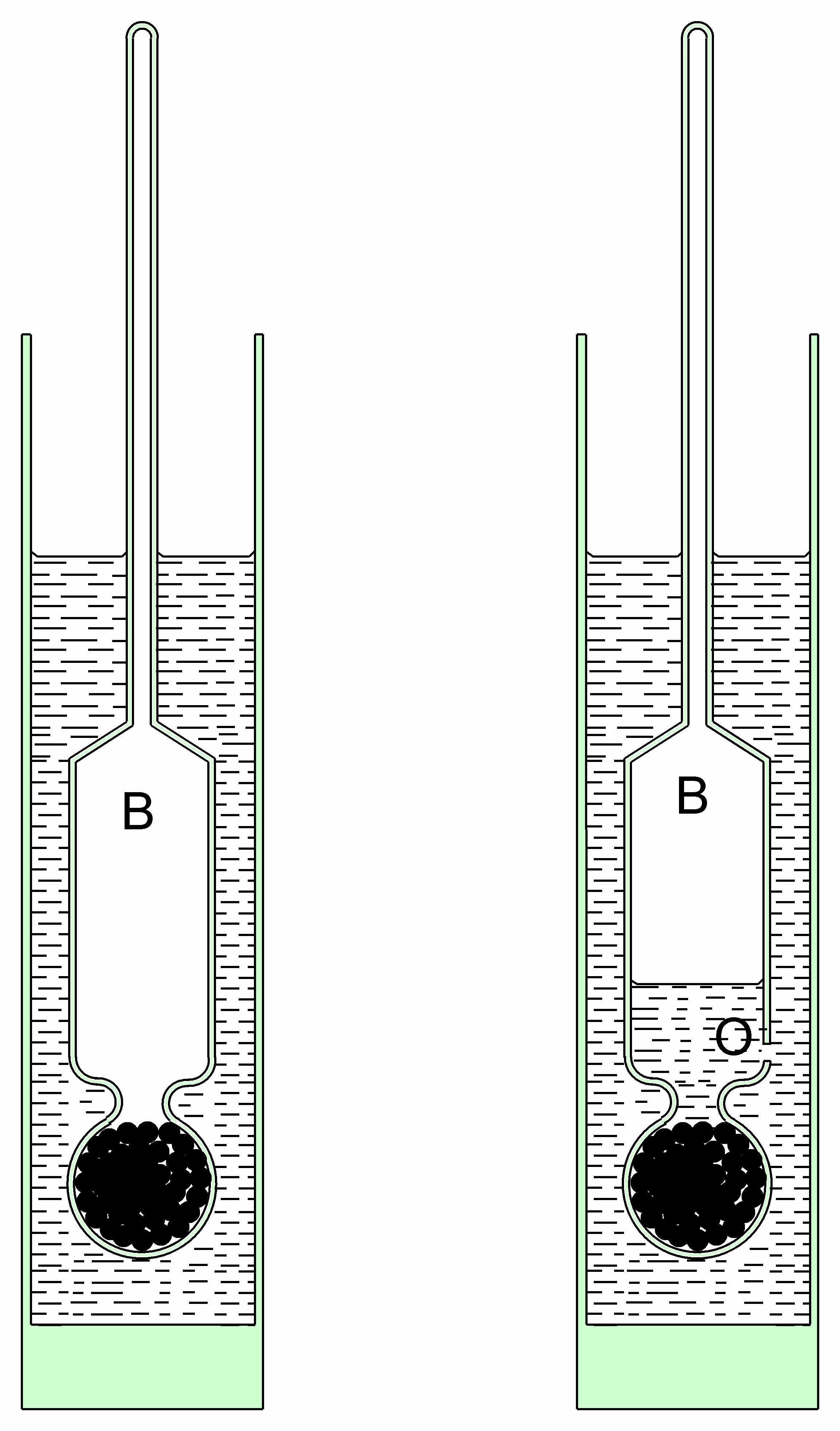
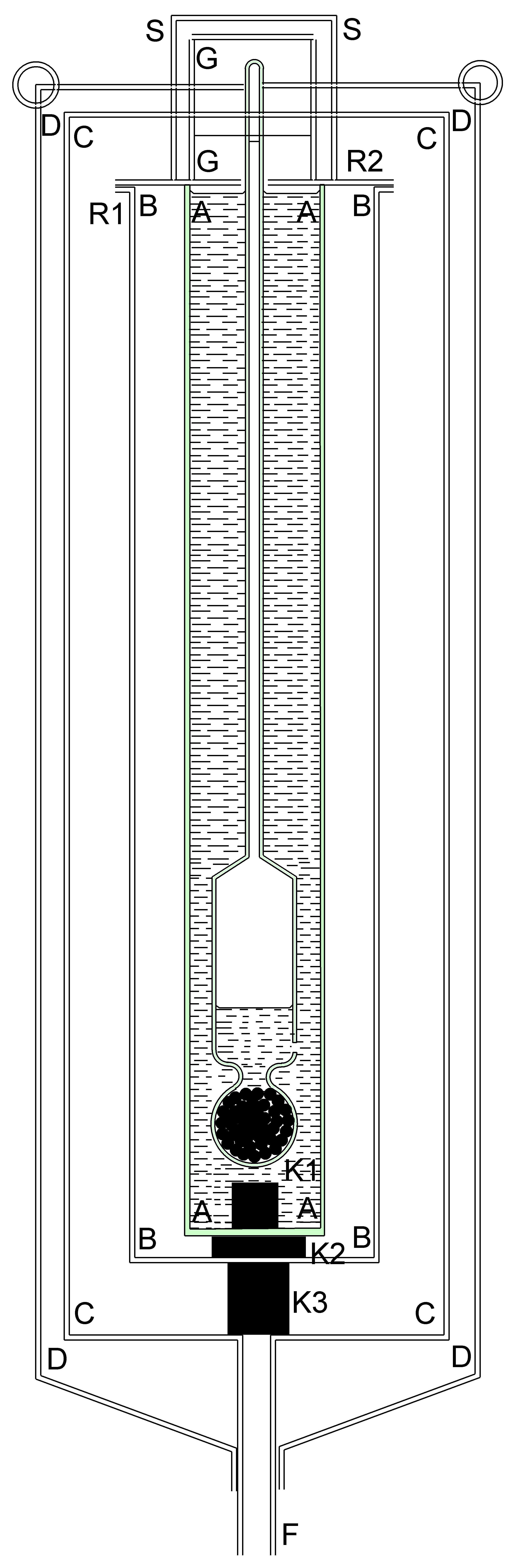
Figure 2. A Hydrostatic barometer designed by Karl Fischer to used as an altimeter. His description translated from the German is as follows: “ The hydrometer, at a suitable height supplied with distilled water and mercury, is immersed with water in a container made out of a pipe A A and A A filled to the brim. A A is immersed in a similar second container B B. Above, B B is soldered on to a circular plate, in the middle of which an opening is left, which allows Cylinder A A to fit exactly into B B. A second similar sheet R2 is attached to R1 by means of a layer of leather and screws, so that A A is sealed against B B in a watertight way. The index mark is closely connected to R2, while two short connecting tubes are soldered into R2, which between them hold a glass tube G G with sealing wax and smooth lead sealing putty. A fine ring mark M M is etched on to G G, on which the position of the hydrometer scale can be read off. The cork stop K1 on the floor of A A serves to protect the glass body against impact during transport, as does the rubber stopper in the glass tube – drawn as dotted - and finally for further protection of the glass tube, a measuring pipe cap S S is screwed into R2.
In order to keep the inner space of A A at a constant temperature, a coat of ice is frozen in between A A and B B, similar to a Bunsen ice calorimeter, and this coat of ice itself is kept from melting by a container filled with ice C C. For the time of the reading, container B B somewhat raised. C C is thermally protected by a further tin container. The space between C – D is filled either with ice or dry sheep’s wool or otherwise with insulation material. The three hooks soldered on to D D are to hang up the instrument in the balloon.
The melted water is drained off through a hose put into F or, if the outside temperature falls below 0º, melted water is allowed to run back through the hose. K1, K2, and K3 show corks.”
Figure 3. The 3-bulb temperature compensated design by Meteormetrics Limited.
Figure 4 Dimensions affecting the hydrostatic stability of the instrument
Figure 5 The dimensions of the instrument required for hydrostatic stability.