
ALL MATERIAL COPYRIGHT KEVIN SCOTT 2011. LINKS TO THIS SITE ARE WELCOME BUT DO NOT COPY MATERIAL FROM THIS SITE TO ANY OTHER WEBPAGE.


If you find this site useful, please support it by making a donation of $1 to help maintain and develop it. Click on the PAYPAL DONATE button to do this safely. But there is no obligation - please avail yourself of the information and facilities of the site at no charge.
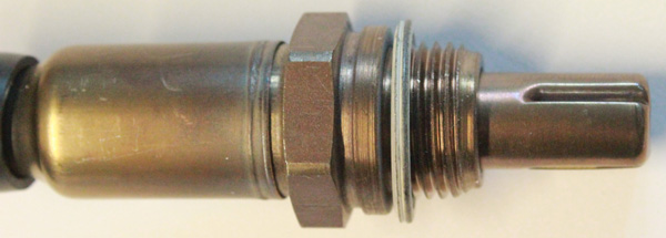
This page describes the realisation of a useful sensor for oxygen across at least three order of magnitude, by utilising a standard automotive fuel/air ratio sensor normally used to provide information to the engine management system of a car on the composition of the exhaust gas. A generic version of the automotive sensor is shown to the left. It is about the size of a spark plug and has the same 18mm metric thread as the latter.
In the application described here, the sensor is modified to function as a monitor for oxygen concentrations in gas flows encountered in laboratory measurements of oxygen diffusivities and other applications.
The simplest form of a zirconia solid electrolyte detector for oxygen, consists of a zirconia tube with a platinum wire sealed to the inside surface and a similar wire fused to the outside, the tube being mounted in a tubular furnace at 600 °C. An electrometer amplifier can be used to monitor the emf between the two Platinum electrodes.
At 600 °C, Oxygen ions are mobile in the Zirconia which therefore becomes an electrolyte at this temperature. The cell the operates as an oxygen concentration cell and thus gives an EMF proportional to the log of the ratio of O2 partial pressures on either side of the cell.
Reducing agents such as Hydrogen or Hydrocarbons interfere by reducing the apparent concentration of Oxygen.

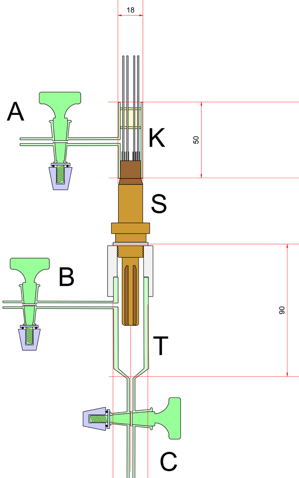
The construction of a suitable laboratory oxygen detector is shown in the photograph and drawing above. The automotive sensor S was modified so that the atmosphere on both sides of the Zirconia element could be controlled and adjusted. The housing on the rear of the sensor was fully welded and therefore vacuum tight except for the port through which the heater and electrode connections were made. This part of the device was modified by adding a borosilicate component K which was secured in place by means of an epoxy cement and wires led out also through a section of epoxy resin. A stopcock A, allowed this side of the Zirconia cell to be evacuated and filled with any gas mixture desired. In cases where the oxygen partial pressure on the sensor side is close to 1 atmosphere, the reference side was left exposed to the laboratory atmosphere, but where trace oxygen concentrations where to be measured, or the sensor side was evacuated, it was found necessary to evacuate the reference side. This was to obviate a small internal leak which was found to exist between the sensor and reference sides of the ZrO2 detector.
Vessel T, fitted with two taps B & C, was sealed to the sensor by means of a PTFE collar, etched with Sodium Naphthalide, and machine for a close fit to the sensor and the tube T.This etched collar was secured to the sensor and the tube T, by means of epoxy resin.
In order to gain an estimate of the interior temperature of the ZrO2 cell, the electrical coefficient of resistance of the cell heater was determined using a Wayne Kerr automatic Bridge attached to the heater connections while the sensor was heated in an oven. The results are shown in the table below:
| Temp | Resistance |
| degC | ohms |
| 22.4 | 3.44 |
| 76.5 | 3.98 |
| 93.5 | 4.2 |
| 103.5 | 4.33 |
| 103.9 | 4.33 |
| 113.5 | 4.48 |
| 120.1 | 4.56 |
| 89 | 4.26 |
| 72 | 4.05 |
| 70.5 | 4.04 |
| 62.9 | 3.96 |
| 55.8 | 3.89 |
| 51.2 | 3.82 |
The calculated temperature coefficient of resistance of the sensor heater was 0.0107 ohms/°C and the resistance at 22.4 °C was 3.44Ω The sensor was probably designed for 12 volt operation, but it was found to be effective at 10 volts with a current of 1.1 amps. This corresponds to a resistance of 9.09Ω and to a working temperature of 544°C At this running temperature, the perforated shield around the sensor reached about 200°C (measured with a thermocouple meter) and the body of the sensor reached about 100-120 °C, which was considered low enough to give the epoxy seals a reasonable life.
The ZrO2 detector was calibrated using a Logarithmic Dilution Vessel(LDV). The LDV was placed in series with the detector and an Argon flow of 34 ml/min was passed through them. 10ml of Oxygen were injected into the LDV and the signal from the ZrO2 detector recorded on a potentiometric recorder. The resultant trace is shown below.
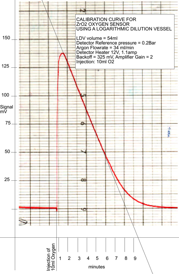
It will be noted that the greater part of the trace is linear as a result of the combination of the exponential decrease in the oxygen concentration from the LDV and the logarithmic relationship between the ZrO2 galvanic output and the ratio of partial pressures either side of the cell. Using the parameters of the LDV, the partial pressure of oxygen passing through the cell at any given time can be calculated and, with the corresponding EMF reading from the trace, a calibration plot can readily be generated. This is shown below:
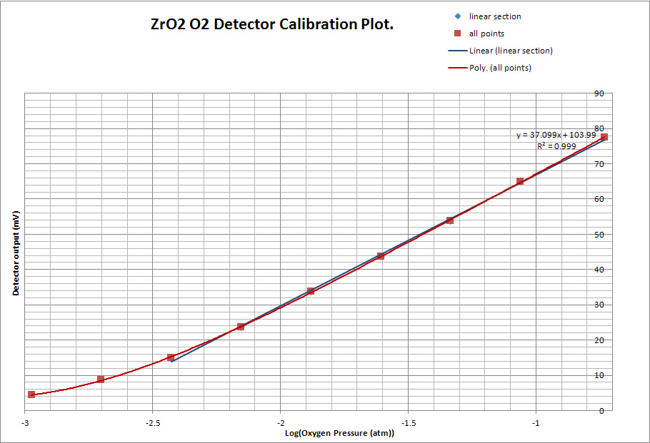
The slope of the this calibration plot corresponds to about 37mV per decade of Oxygen partial pressure and the plot shows a linear section of about two orders of magnitude. The ZrO2 detector is capable of a much wider dynamic range than this, but in this case it is restricted probably by the residual oxygen in the Argon supply.