
ALL MATERIAL COPYRIGHT KEVIN SCOTT 2011. LINKS TO THIS SITE ARE WELCOME BUT DO NOT COPY MATERIAL FROM THIS SITE TO ANY OTHER WEBPAGE.


If you find this site useful, please support it by making a donation of $1 to help maintain and develop it. Click on the PAYPAL DONATE button to do this safely. But there is no obligation - please avail yourself of the information and facilities of the site at no charge.
There are different techniques for vacuum sputtering available by which a metallic surface can be deposited on a substrate for electrical or optical purposes. The most universal is the technique in which a metal is volatilised in a vacuum by heating it using a tungsten filament carrying a current. The metal to be deposited is wrapped as a foil around the filament and after the vacuum has been established, a pulse of current through the filament evaporates the metal which then condenses on the substrate surface. Alternatively, using a copper cathode, an electrical discharge can be used to deposit a copper film on to a substrate with the latter supported on or near the anode. This latter technique is easier to set up and is less demanding of the quality of the vacuum needed, but it is limited in practice to the use of copper as the deposited metal. This is because the technique exploits the ready formation of Cu2- dimeric ions which are liberated from the cathode surface and are discharged on to the receiving surface. This paper reports the application of vacuum copper deposition for the production of optical filters, mirrors and optical slits.
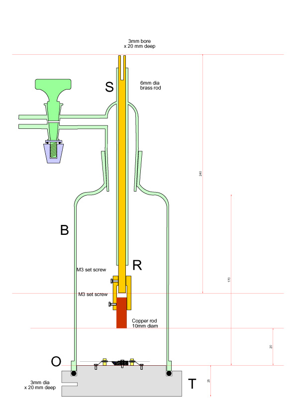
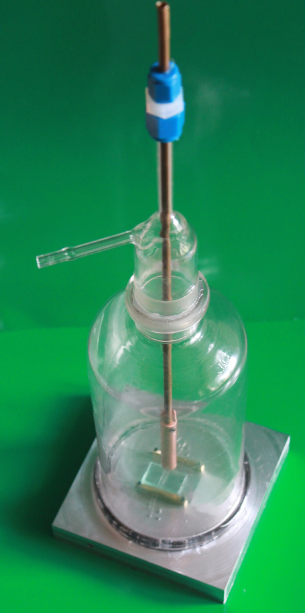
The apparatus used for copper sputtering is shown to the left. It consists of a machined aluminium base T, machined to support objects to be coated and provided with a 4mm blind hole to act as a socket for a banana plug. The base T carries a bell jar B which is vacuum sealed to the base by a vacuum-greased O ring. A central glass tube S carries a brass shaft R which terminates at its lower end with a copper rod as shown. The upper end of the brass shaft is sealed to the tube S by a nylon swagelock reducing union drilled out to carry R & S and provided with O rings to secure a good vacuum seal. Rod R is bored with a 4mm axial hole to accommodate a 4mm banana plug. The bell jar is evacuated by means of a rotary pump to a pressure of about 0.3MB.
NB: THE COPPER SPUTTERING METHOD EMPLOYS A 6000 VOLT NEON TRANSFORMER CAPABLE OF DELIVERING SUBSTANTIAL CURRENT WHICH IS DANGEROUSLY LETHAL. THIS IS EXACERBATED BY THE FACT THAT ONE SIDE OF THE HIGH VOLTAGE SUPPLY IS GROUNDED. THIS MEANS THAT CONTACT WITH THE OTHER SIDE ALONE CAN BE FATAL. THE APPARATUS SHOULD BE DESIGNED IN SUCH A WAY THAT NO HUMAN PHYSICAL CONTACT IS POSSIBLE WITH HIGH VOLTAGE DURING OPERATION.
The electronics are shown in the schematic below.
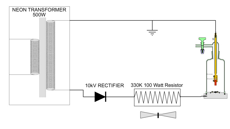
The transformer is a standard 6kV, 500W device used to power commercial neon signs. The rectifier is a 10kV PIV 0.5amp silicon device while the 100W 330K resistor was made by wiring 10 33k 10W resistors in series. An electric fan was provided to dissipate heat from this array. It was found necessary to ground the cathode side of the sputtering chamber to prevent corona discharge in the interconnecting tubing to the pump. If such corona discharge was permitted to occur, flexible vacuum tubing could become perforated by arcing and the vacuum caused thereby to fail.
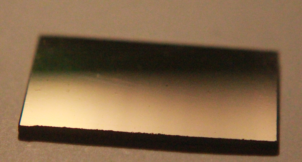
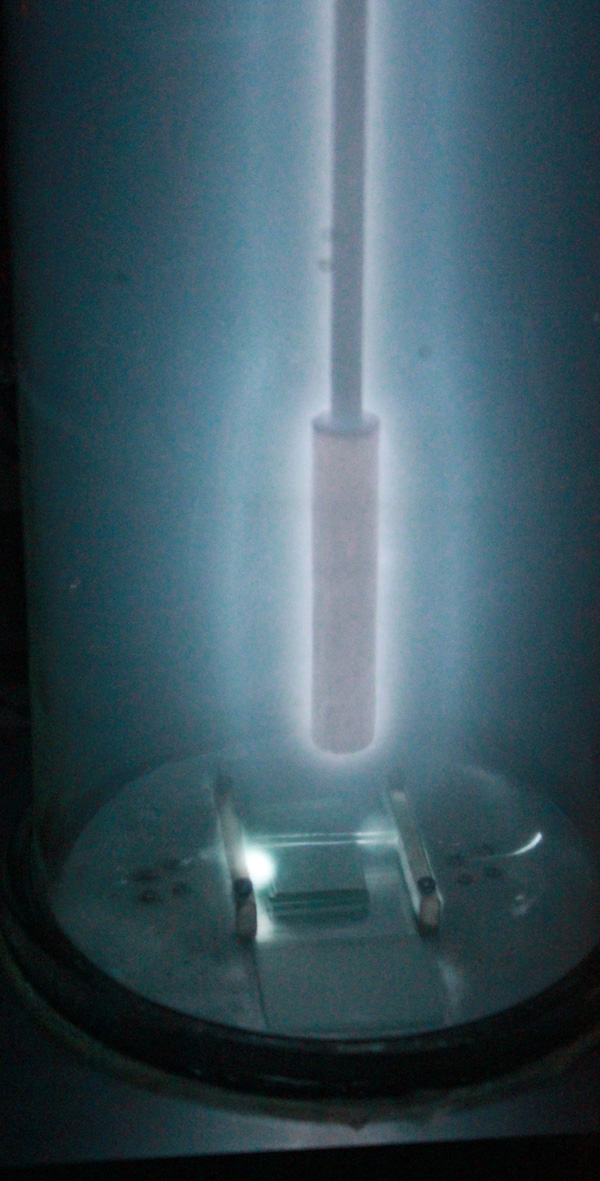
It was found that, with a current of about 15mA, the maintenance of a continual discharge for a period of 2 hours produced a useful semi-transparent mirror which could be used as a beam splitter or a filter. The same current maintained for 4 hours produced a brilliant reflective surface with no discernible transmission.The mirror surface was very smooth, highly reflective, uniform and with no blemishes.
The deposited metal surface was also robust and securely attached to the glass substrate. It could be scraped off with a scalpel blade, but was entirely resistant to being polished with a soft cloth. When scratched with a blade, only the metal directly in contact with the blade was removed, the surrounding areas were not affected and the metal film did not lift.
Slit production will be possible using the technique, but the masking material cannot be metal. It is thought that nylon monofibre might well be suitable as masking material for slit production.