
ALL MATERIAL COPYRIGHT KEVIN SCOTT 2011. LINKS TO THIS SITE ARE WELCOME BUT DO NOT COPY MATERIAL FROM THIS SITE TO ANY OTHER WEBPAGE.


If you find this site useful, please support it by making a donation of $1 to help maintain and develop it. Click on the PAYPAL DONATE button to do this safely. But there is no obligation - please avail yourself of the information and facilities of the site at no charge.
Analogue multimeters have been substantially eclipsed by digital instruments which have won a favoured place on the electronics workbench owing to their precision and ease of reading. But in this digital revolution some assets and advantages of analogue instruments have been lost and there is a case for the revival of analogue meters in many circumstances. Advantages of a moving coil multimeter include:
1) Better readability of slowly changing signals and drifting voltage and currents.
2) Better estimation of signal stability over time
3) Small voltage changes are more readily recognised at a glance.
4) Analogue multimeters can be entirely constructed using passive components which enable them to hold their calibration for longer.
5) Using only passive components Analogue multimeters can deliver accurate voltage and current measurements with no dependence on a battery or on its state of exhaustion.
On the other side, digital instruments can be read to a greater number of decimal places, although often the number of digits is not justified by the quoted accuracy. Digital instruments are more compatible with datalogging functions, computer interfacing, and post-measurement processing. If the reading is static, digital instruments are easier to read and possibly less vulnerable to operator error.
The author's own preference, however, often lies with the analogue instrument. In an experiment where several electrical quantities have to be monitored and measured, it is easier to see at a glance that all is well with the set-up if analogue measurements are employed. So a collection of analogue multimeters form an important element of the experimentalist's armoury and thus is worthy of some space in these pages.
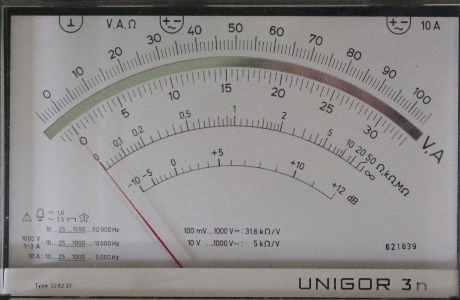
Multimeter scales are usually divided into 60 - 120 divisions, depending upon the arrangement of the ranges. The Unigor 3n, for example, has ranges in orders of magnitude interspersed with factors of 3. Using the antiparallax mirror, it is possible to interpolate, using a lens, between the finest divisions to a factor of 10 or possibly, with keen eyesight, to a factor of 20. This means that on the 10 volt range of the Unigor 3n multimeter, it would be possible to measure a voltage to within 10 mV or possibly 5mV. This is an order greater than the quoted accuracy of the meter and is comparable with the readability of a 3-1/2 digit digital multimeter.
All the Unigor series of multimeters are provided with an anti-parallax mirror. The plates on the right show the value of this mirror built into the scale.

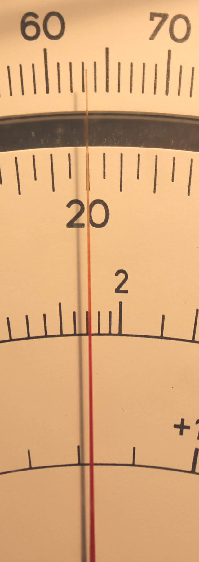 On the far right, the camera shot corresponds with the eye being at an acute angle to the normal from the scale. This results in an inaccurate reading of the position of the needle with respect to the scale. The picture on the left shows the view normal to the scale rendering an accurate reading of the needle position. All the user has to do to take advantage of this is to read the scale when the reflection of the needle in the mirror lies exactly behind the needle itself. Parallax error is thus neatly avoided.
I do not have an exhaustive list of the Unigor Multimeter Models, but here are some:
| MODEL | PURPOSE | DCV SENSITIVITY | MaxDCvolts | MaxDCamps | ACVSensitivity | Other ranges | Battery |
| 1s | power circuitry testing | 3333ohms/volt | 1200 | 30A | 3333ohms/V | Rx5 | R10 |
| 1p | power circuitry testing | 3333ohms/volt | 1200 | 30A | 3333ohms/volt | Rx5 | R10 |
| 1n | power circuitry testing | 3333ohms/volt | 1200 | 30A | 3333ohms/volt | Rx5 | |
| 3s | electronics testing | 1KV | 5A | Rx5 Cx2 | |||
| 3p | electronics testing | 25Kohm/V | 5KV | 5A | 2Kohm/V | Rx5,Cx2 | R10 |
| 3n | electronics testing | 31.6kohm/volt | 1KV | 10A | 5kohm/V | Rx5 | 1.5V D cell |
| 4n | electronics testing | 1KV | 1A | ||||
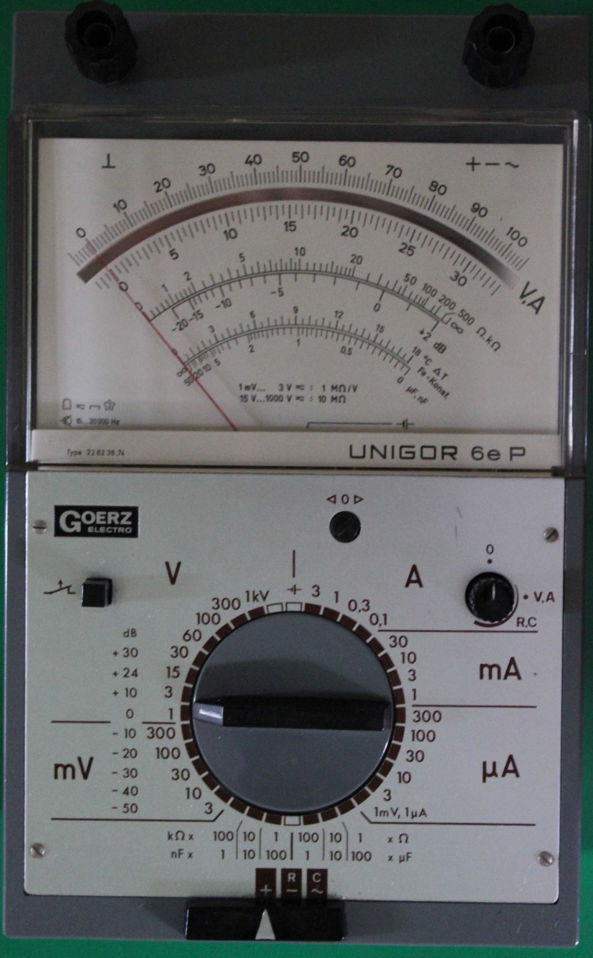
| 6e | High impedance circuitry | 1Mohm/volt | 1KV | 3A | 1Mohm/V | Rx6 Cx6 Tx2 | 4x C cells |
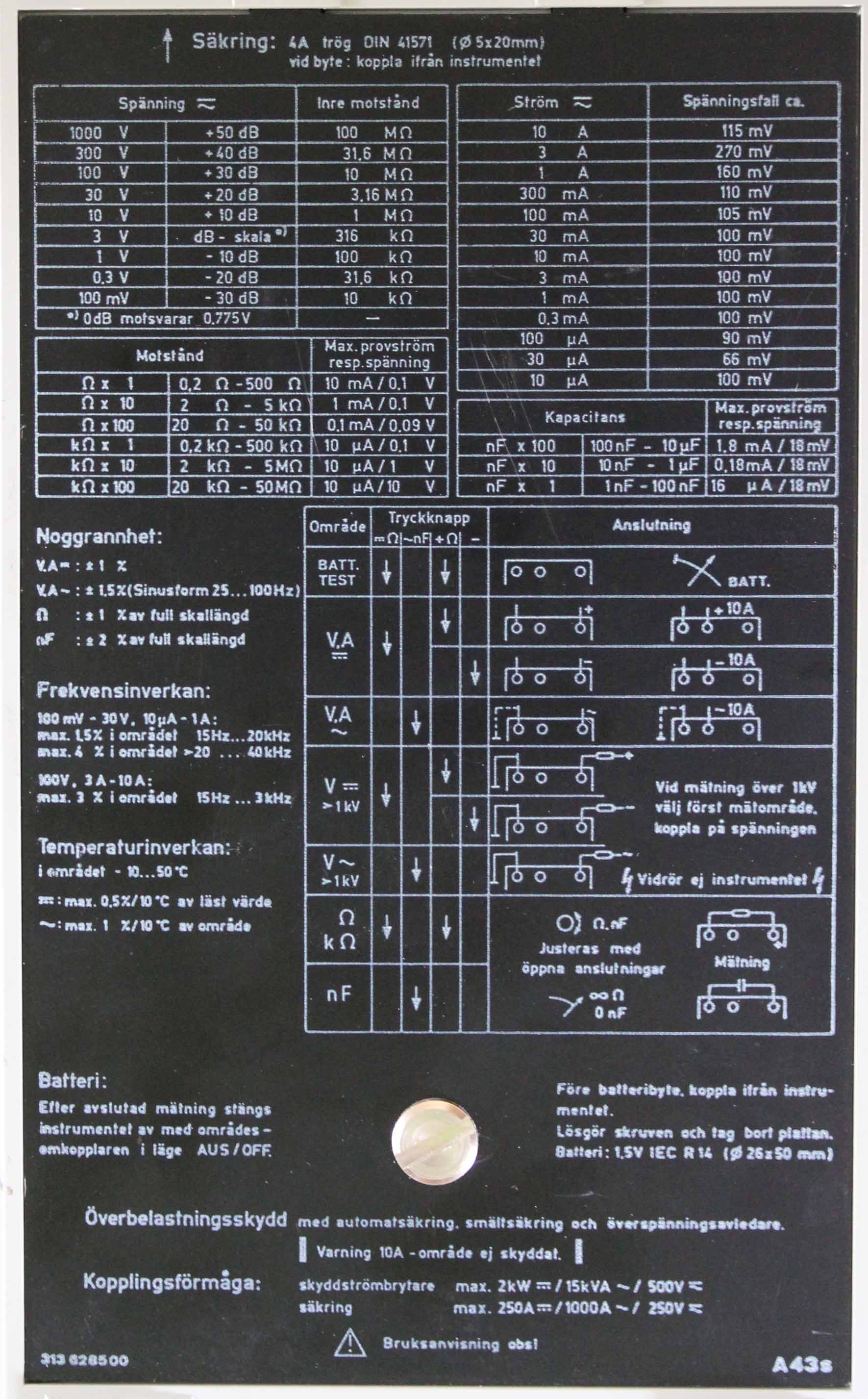
| A43 | electronics testing | 100Kohm/V | 1KV | 10A | 100Kohm/volt | Rx7,Cx3 | 1x C cell |
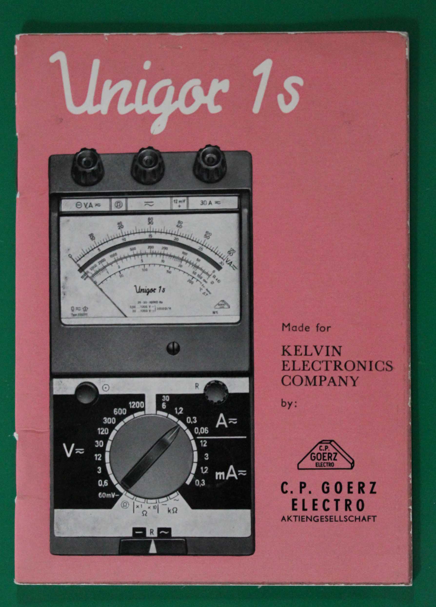
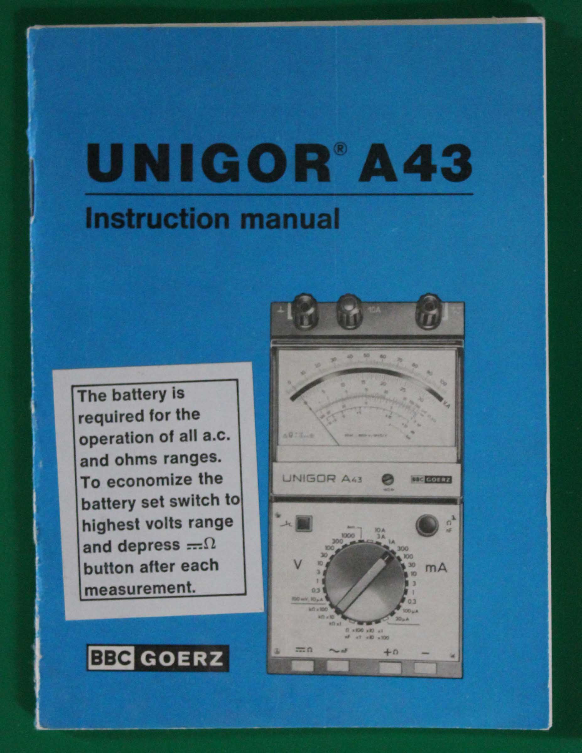
At present, the author has two manuals available which can be downloaded as pdf documents by clicking on the two images to the right. They contain all necessary operational information, data on accuracy and sensitivity and a circuit diagram.
A useful feature of the Unigor series of multimeters is the essential information which is made available to the user on the rear of the instrument. Unfortunately, being in this position, the information can readily be obliterated by mechanical scuffing of the base plate in use, or by the effect of solvents. The author has two instruments with backplates in reasonable condition which are reproduced below:
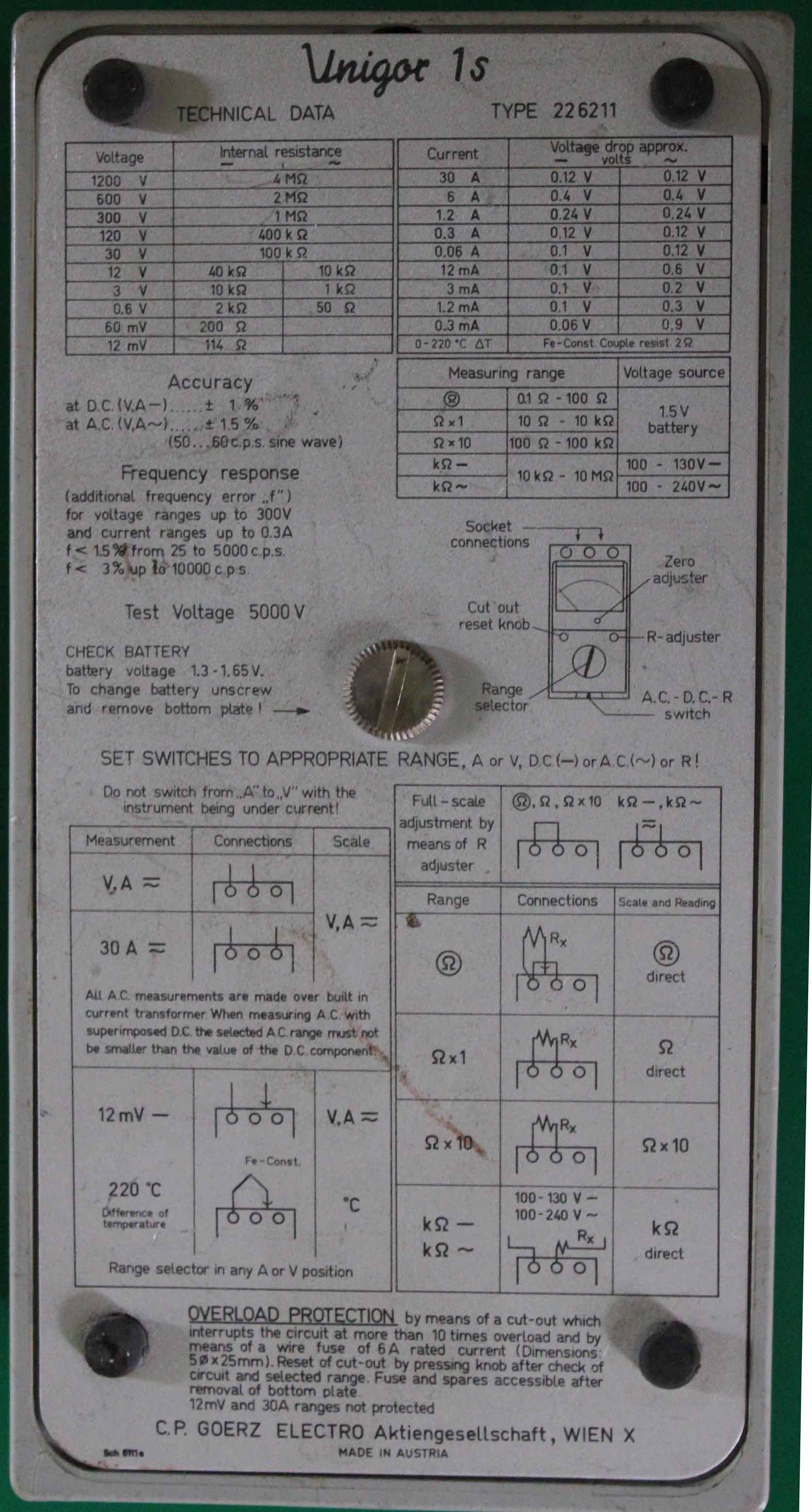
To a great extent the operation of Unigor multimeters does not require specialised knowledge: on most ranges the instruments perform as would be expected. It is on the low ohms range and on the capacitance measuring ranges that some guidance will be needed. In the case of the 1s instrument, the low ohms range is accessed by shorting together the left & centre terminals and placing the unknown resistance between the shorted terminals and the left hand socket on the top panel. A similar arrangement is employed on the Unigor 3p.
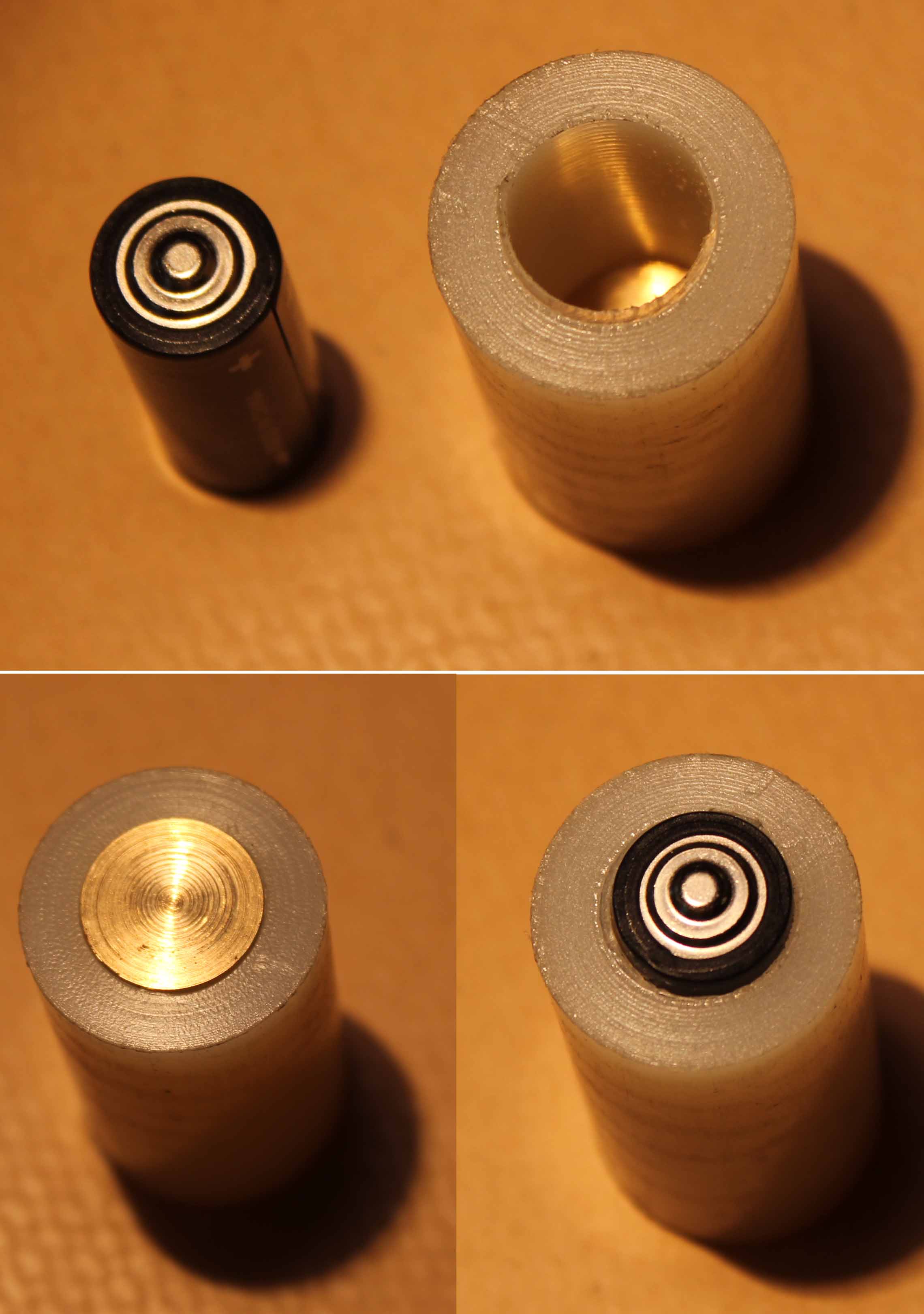
As indicated in the table above, most Unigor meters use a C type cell or a D type, or in the case of the 6E, four C cells. The 1S & 1P instruments use a a R10 cell which is no longer manufactured. There are two ways of overcoming this: A battery containing two R10 cells in series is still available as a 2R10 and this can be carefully opened to extract one of the cells which will fit the instrument. Alternatively, a MN9100 cell, which is smaller than the R10 can be employed with a suitable turned sleeve to enable it to fit the battery compartment. The plate to the right shows such a sleeve, turned in nylon with a brass insert to act as the negative terminal. In the five models used by the author, the only point of difficulty encountered with the instruments was a very small degree of corrosion in the battery compartment. It was slight and easily rectified, and beyond this, the instruments have always worked faultlessly on demand. One of these instruments ( Unigor 1s) has done so for the author for over 40 years.
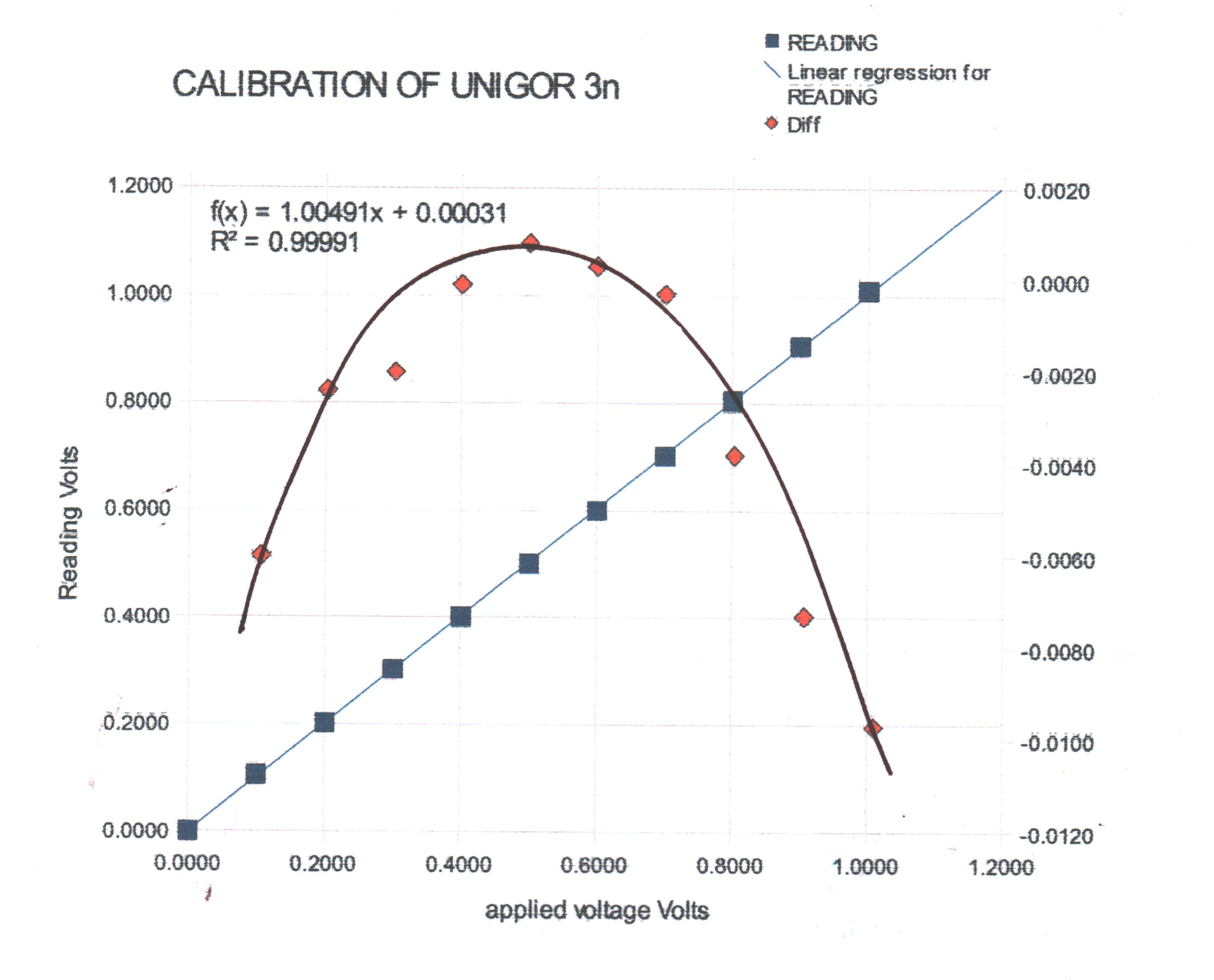
As an example, the plot on the right shows the data from a calibration of the 1 volt range of a Unigor 3n using Ronan calibrator Type X85. The data is also given in the following table:
| TEST V | READING | Diff |
| 0.0000 | 0.0000 | 0.0000 |
| 0.2006 | 0.2030 | -0.0024 |
| 0.1000 | 0.1060 | -0.0060 |
| 0.3010 | 0.3030 | -0.0020 |
| 0.4004 | 0.4005 | -0.0001 |
| 0.5008 | 0.5000 | 0.0008 |
| 0.6006 | 0.6003 | 0.0003 |
| 0.7007 | 0.7010 | -0.0003 |
| 0.8002 | 0.8040 | -0.0038 |
| 0.8997 | 0.9070 | -0.0073 |
| 1.0003 | 1.0100 | -0.0097 |
The accuracy of the instrument is well within the quoted 1% especially in midscale readings which are within 0.1%. The parabolic error plot may arise from the characteristics of the moving coil taut suspension.