
ALL MATERIAL COPYRIGHT KEVIN SCOTT 2011. LINKS TO THIS SITE ARE WELCOME BUT DO NOT COPY MATERIAL FROM THIS SITE TO ANY OTHER WEBPAGE.
If you find this site useful, please support it by making a donation of $1 to help maintain and develop it. Click on the PAYPAL DONATE button to do this safely. But there is no obligation - please avail yourself of the information and facilities of the site at no charge.
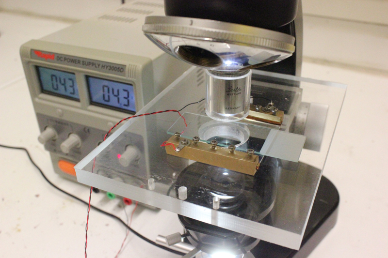
Microscopes with heated stages are available, but Indium Tin Oxide coated glass presents an attractive alternative. 1 mm thick glass with such a conductive coating is readily available at low prices and for this study panels 50mm x 50mm were obtained from Adafruit for about $5.95 apiece.
The samples obtained were inspected for suitability as material for microscope slides and appeared blemish free and were checked on a polarising microscope for any possible birefringence and none detected. Conveniently, Adafruit also supplied copper tape with an electrically conductive adhesive backing. With two machined brass strips, this copper tape applied to the edges of the Indium Tin Oxide coated glass produced an electrically heatable glass slide suitable for chemical microscopy.
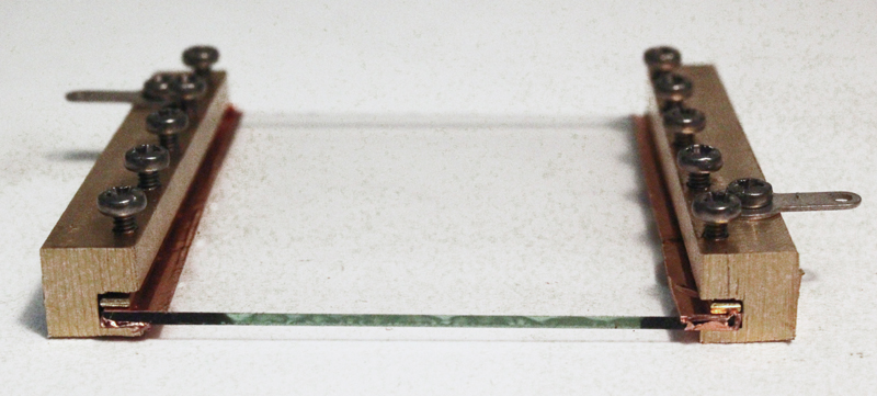
Indium Tin Oxide is a semiconductor material and therefore would not be expected to exhibit the ohmic characteristics of metals. Nor, indeed, would the oxide layer be expected to show the same temperature dependence of resistivity normally associated with metals.
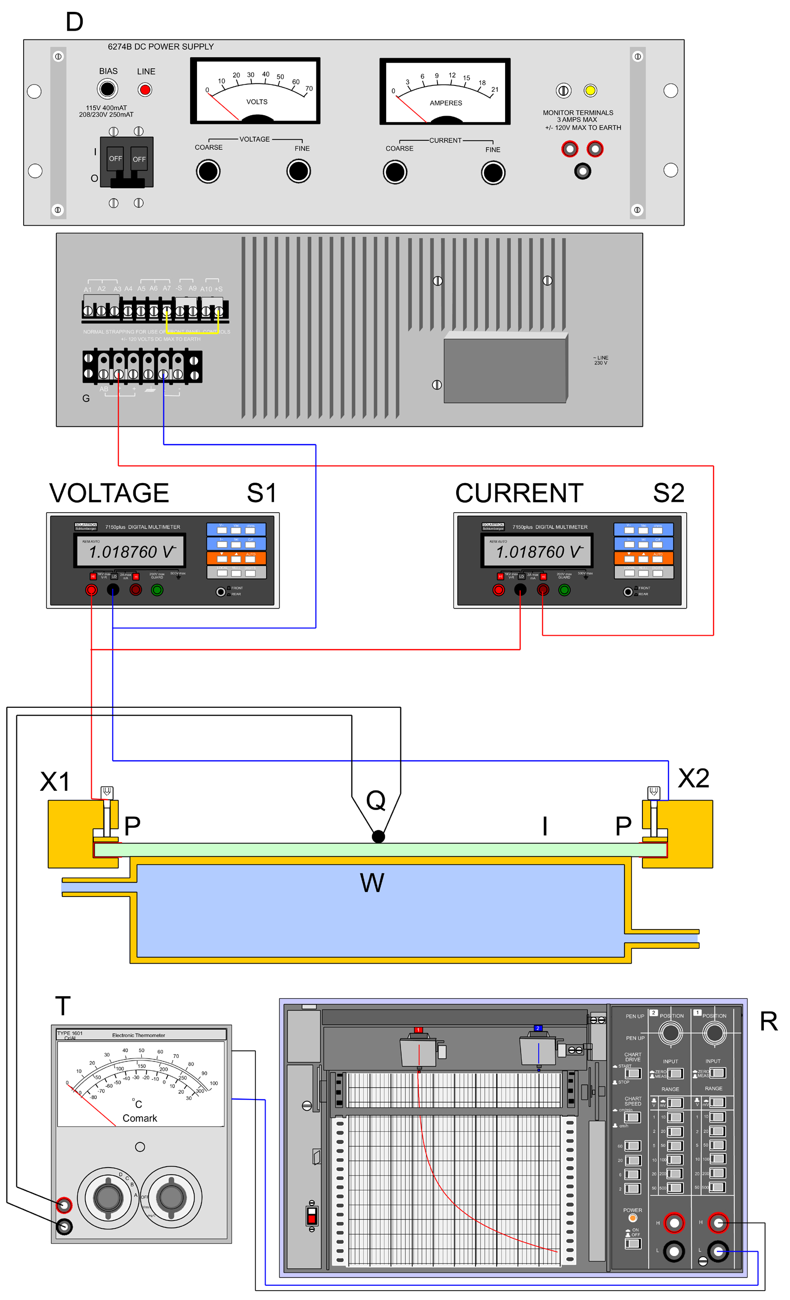
In order to investigate these characteristics, the 50mm x 50mm Indium Tin Oxide coated glass slide fitted with the brass connecting strips, X1 & X2 was set up as in the sketch. For isothermal tests a water-cooled heatsink W was thermally attached to the glass slide using thermally conductive grease and a chrom-alumel thermocouple mounted in contact with the upper surface which was Indium Tin Oxide coated. Voltage across the slide and current through it were monitored using Solartron 7150 6½ digit multimeters and the temperature was read using a Comark Type 1602 thermocouple meter, T, the output of which was fed to a recorder R.
For the electrothermal investigation the heatsink W was removed and the slide I allowed to rest on a ceramic tile for experiments up to 200°C. After each change of current, the temperature was allowed to stabilise by observing the trace on recorder R, before readings of current voltage and temperature were taken. 200°C was considered a maximum required by the application, although the glass itself is rated to 300°C. On-slide crystallisations from solution would thus be readily accessible, but from the melt would be limited to only a few low-melting compounds.
The data obtained for voltage/current measurements at constant temperature are shown in the table below, right
| Voltage | Current | Temperature |
| Volts | milliamps | °C |
| 0.977 | 111.43 | 14.2 |
| 1.448 | 164.98 | 14.4 |
| 1.704 | 192.4 | 14.4 |
| 1.909 | 215.2 | 14.5 |
| 2.201 | 244.8 | 14.6 |
| 2.201 | 241.3 | 14.7 |
| 2.47 | 269.5 | 14.9 |
| 2.72 | 296.6 | 15.0 |
| 3.08 | 337.1 | 15.0 |
| 3,698 | 418.4 | 15.5 |
| 4.199 | 477.0 | 16.0 |
| 4.95 | 573.3 | 17.0 |
| 5.523 | 654.0 | 18.0 |
| 6.030 | 726.0 | 18.6 |
| 6.700 | 815.0 | 19.9 |
| 7.470 | 915.0 | 21.0 |
| 8.32 | 1039 | 24.0 |
| 9.17 | 1153 | 26 |
| 9.97 | 1261 | 28 |
The corresponding plot is shown below:
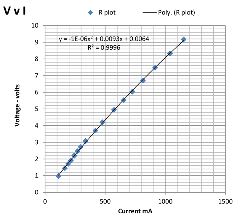
The plot is not linear, partly because of the slight increase in temperature observed with increasing current. It can be fitted empirically to a parabola with a correlation coefficient of 0.9996 as shown on the plot. The slope of the plot gives the resistance of the glass plate. At low current the apparent resistance is about 8.8 ohms falling to 8 ohms at 1 amp current.
By removing the heatsink, and repeating the experiment while allowing the glass slide to reach a steady temperature at each voltage setting, it was possible to determine the dependency of resistance upon temperature, and the power required to enably any particular temperature to be reached.
| Voltage | Current | Temperature | Power | Resistance |
| V | mA | °C | Watts | Ohms |
| 1.103 | 110.3 | 24 | 0.12166 | 10.00 |
| 1.568 | 152.9 | 25.6 | 0.2397 | 10.255 |
| 2.298 | 215.3 | 29.3 | 0.4948 | 10.673 |
| 2.938 | 276.0 | 34 | 0.8109 | 10.6449 |
| 3.398 | 338.2 | 38.3 | 1.1492 | 10.047 |
| 3.922 | 412.8 | 47.0 | 1.619 | 9.501 |
| 4.381 | 466.5 | 54 | 2.044 | 9.391 |
| 4.987 | 541.4 | 64.2 | 2.700 | 9.211 |
| 5.443 | 597.2 | 72.0 | 3.251 | 9.1141 |
| 5.883 | 653.8 | 80.0 | 3.846 | 8.998 |
| 6.471 | 711.2 | 91 | 4.602 | 9.099 |
| 7.102 | 781.4 | 112.8 | 5.550 | 9.089 |
| 7.774 | 857.0 | 127 | 6.662 | 9.0711 |
| 8.218 | 909.5 | 137 | 7.474 | 9.036 |
| 8.769 | 974.0 | 149 | 8.541 | 9.003 |
| 9.317 | 1023.4 | 164 | 9.535 | 9.104 |
| 9.830 | 1073.2 | 173 | 10.55 | 9.1595 |
| 10.43 | 1128 | 183 | 11.77 | 9.246 |
| 11.41 | 1224 | 201 | 13.97 | 9.322 |
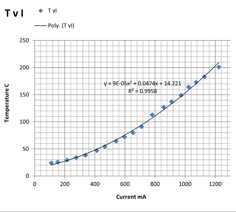
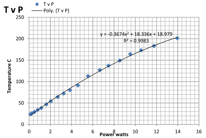
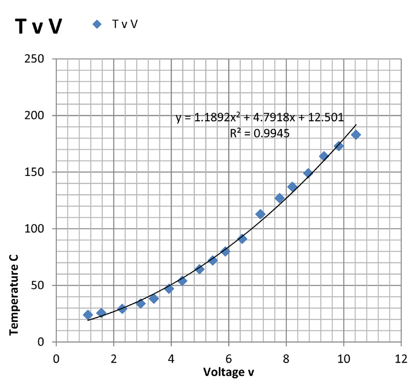
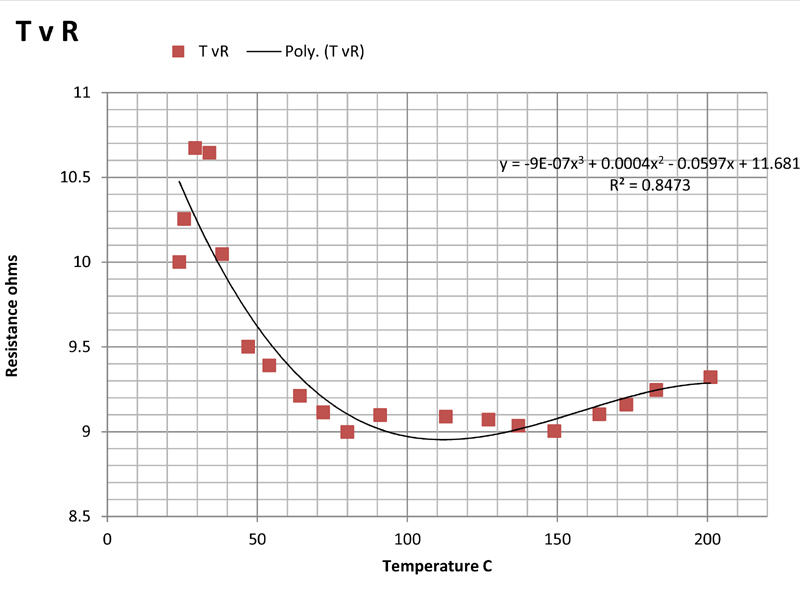
The above plots show the temperature plotted against current (TvI), power (TvP), voltage (TvV), and resistance (TvR). Of these, the first three are somewhat non-linear but show monotonic behaviour as might be expected. The plots are least-squares fits of the data to second order polynomials which give a purely empirical description of the relationship between the variables.
The last plot of resistance versus temperature is far from linear, the resistance falling with rising temperature. This is what might be expected from a semiconductor oxide layer. The fact that the resistance does not change very much between 100°C and 200°C, indicates that the resistance cannot be used as a measure of the temperature and that microcalorimetric control of the temperature using resistance will not be possible. This is regrettable as it would have enabled calorimetric measurements to be made on reactions and processes taking place on the slide.
It was resolved either to use the TvV plot to estimate the temperature of the slide in use, or to attach a surface mount platinum resistance thermometer to the slide.