
ALL MATERIAL COPYRIGHT KEVIN SCOTT 2011. LINKS TO THIS SITE ARE WELCOME BUT DO NOT COPY MATERIAL FROM THIS SITE TO ANY OTHER WEBPAGE.


If you find this site useful, please support it by making a donation of $1 to help maintain and develop it. Click on the PAYPAL DONATE button to do this safely. But there is no obligation - please avail yourself of the information and facilities of the site at no charge.
A series of small tubular heaters were required for a prototype instrument in which temperatures had to be accurately maintained and heat losses minimised. Other design constraints meant that the ends of the tubes had to be open and unjacketed while a vacuum jacket extended the length of the component. The arrangement is shown in figure 1.
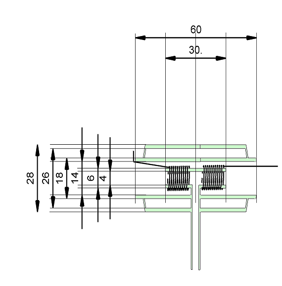
The inner Tee had a 1mm pitch helical groove ground into each horizontal limb. This was achieved by means of a diamond cutting wheel mounted in the chuck of a small drill, itself mounted on the cross-slide of a screw-cutting lathe. A length of 6mm diameter borosilicate glass tubing was mounted in the chuck of this lathe and the helix ground 0.5mm deep in two sections. After fire polishing and annealing the tube, the side-arm was added between the two helical ground sections. The heater wire was 0.5mm diameter monel or stainless steel. These were chosen because they have a relatively high temperature coefficient of resistance which was important for precise temperature control. The windings were secured in place by a thin coating of Ceramabond 569 (Aremco Products Inc., PO. Box 517, 707-B Executive Boulevard, Valley Cottage, NY 10989 )
Heating and temperature control of the winding was achieved by connecting the windings in series as one arm of a Wheatstone bridge with fixed values for the other arms. The out of balance voltage from the bridge was amplified and used to control the current passing through the bridge via a power transistor. The fixed resistors in the bridge were chosen such that the bridge would be balanced if the heater coils were at the desired temperature. The circuit was thus arranged to adjust, automatically, the current flowing through the heater coils to maintain them at this chosen temperature.
By measuring the voltage across the heater and the current though it, the total power dissipated by it was readily determined. The arrangement thus constituted a microcalorimeter with which changes in power dissipation at a fixed temperature could easily be measured. This arrangement was admirably suited to the task of determining the thermal advantage of a vacuum jacket and the further advantage of internal silvering of the jacket. The procedure was straightforward. The bridge was adjusted to bring the temperature of the heater to one of three selected temperatures and the power dissipation allowed to come to a steady state with 1 atmosphere pressure in the jacket. The voltage and current measurements were taken. The jacket was then connected to a high vacuum line capable of a vacuum of about 5 x10⁻⁵ torr, the power dissipation allowed to stabilise and then measured as before. The dissipation at 1 atmosphere was remeasured. This whole procedure was repeated at three temperatures.
The jacket was internally silvered using the procedure published by Smith (1), and produced a brilliant, uniform mirror on the inside surface of the jacket. It was carefully rinsed with distilled water and then pumped down to 5 x10⁻⁵ torr for several hours. The thermal measurements described above were then repeated.
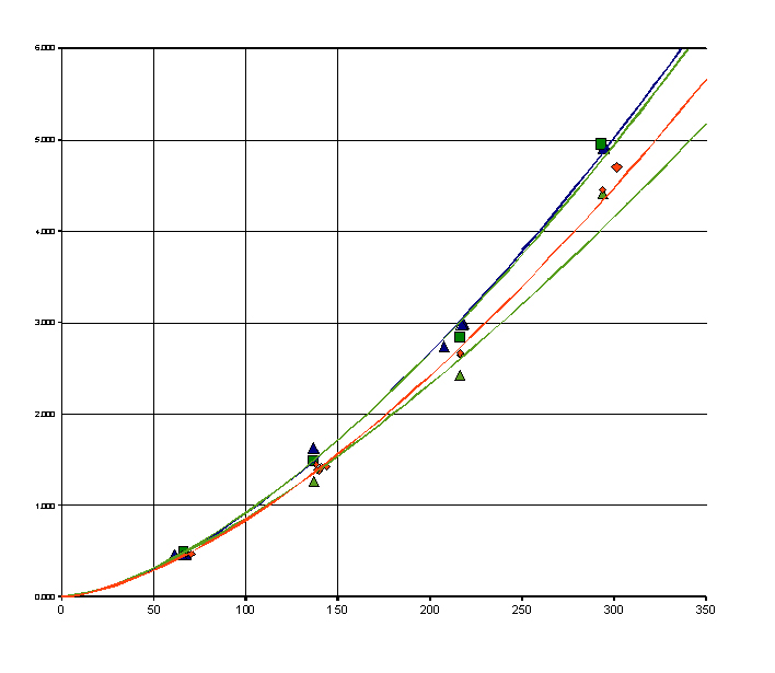
Figure 2 gives a graphical representation of the results. Power dissipated is plotted against temperature for four different conditions: a) no vacuum, no silvering, b) vacuum without silvering, c) silvering without vacuum, and d) silvering with vacuum. Several observations may usefully be made:
a) The thermal advantage offered by a silvered vacuum jacket in this tubular configuration where considerable heat will be convected away via the tubing ends, is very small at low temperatures and rises to about 18% at 300 degrees.
b) As expected the thermal advantage increases with increasing temperature. The curves in figure 2 are power functions of the form Power = ATn where A is a constant and n varies between 1.43 and 1.55.
c) There seems little advantage in silvering a non-evacuated jacket at least in the temperature range examined. This might suggest that the outer silvered layer is more efficient than the inner and is only effective if the intervening space is evacuated.
d) The most important observation is that silvering is as significant as the vacuum, even in the temperature range examined. With the geometry of this particular heater, it was not expected that the vacuum jacket would have a very large effect. However, silvering the jacket doubles its insulating power.