
ALL MATERIAL COPYRIGHT KEVIN SCOTT 2011. LINKS TO THIS SITE ARE WELCOME BUT DO NOT COPY MATERIAL FROM THIS SITE TO ANY OTHER WEBPAGE.


If you find this site useful, please support it by making a donation of $1 to help maintain and develop it. Click on the PAYPAL DONATE button to do this safely. But there is no obligation - please avail yourself of the information and facilities of the site at no charge.
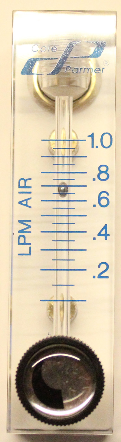
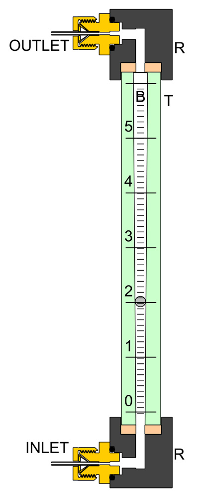
Rotameter flow meters are very convenient in-line monitors for flow rates of liquids and gases. A typical example is shown (right) for flow rates of 0.1 - 1 litre per minute air, and the main design features of the instrument are shown diagrammatically on the left. They have a tube T with a tapered bore B in which is retained a float of a diameter only slightly less than the narrowest part of the bore B. fluid is admitted at the lower end via the connection block R, passes up the measurement tube and is expelled via the upper block. If the flow rate lies in the appropriate range, the float is lifted by the moving fluid to a point where the downward force of gravity acting on the float is matched by the viscous drag of the fluid as it passes through the annular space between float and the tube wall.
Rotameters are generally capable of a range of a single order of magnitude of flow rate, but by adjusting the taper and the float diameter and material at manufacture, that range can be set to lie anywhere between only a few millilitres of a gas per minute to several litres per minute. This brief note describes some simple means of changing the range of a particular rotameter to meet an application which requires a somewhat different flow range than that specified for the instrument in question.
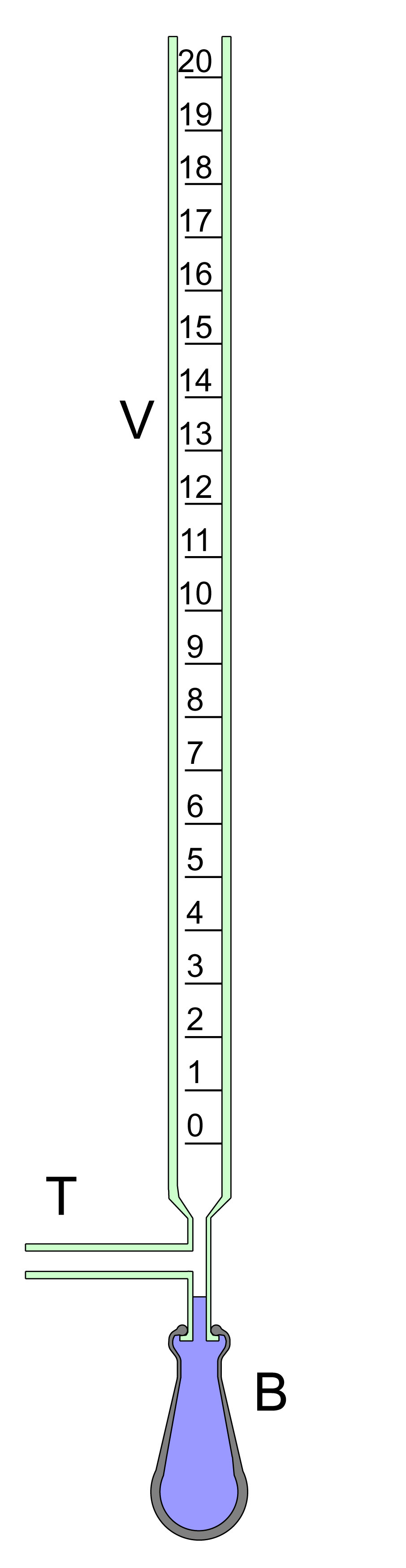
To calibrate rotameters in the lower flow rate ranges, the instrument to be calibrated is placed in series with the appropriate gas supply metered through a need valve and a bubble flowmeter of the type illustrated left connected to its outlet. The flow rate is adjusted to convenient readings on the rotameter and the flow rate determined by timing the ascent of soap bubbles up the calibrated tube using a stop watch. The rubber teat is filled with a suitable soap solution so that bubbles can be introduced into the gas stream when required.
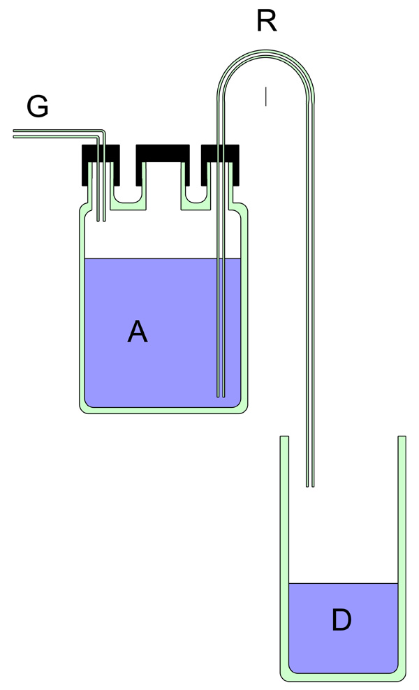
The apparatus shown to the right can be used for the calibration of rotameters designed for higher flow rates. The Rotameter to be calibrated is placed in series with a gas supply with a flow rate adjustable by a needle valve. The flow rate is adjusted to give the desired reading on the rotameter, the gas then turned off and a measured volume of water is placed in the upper vessel A. The outlet of the rotameter is connected to inlet G. The gas supply is then turned on and the time taken for the water in A to be expelled into vessel D via tube R, is timed with a stopwatch. This process is repeated for other settings of the rotameter.
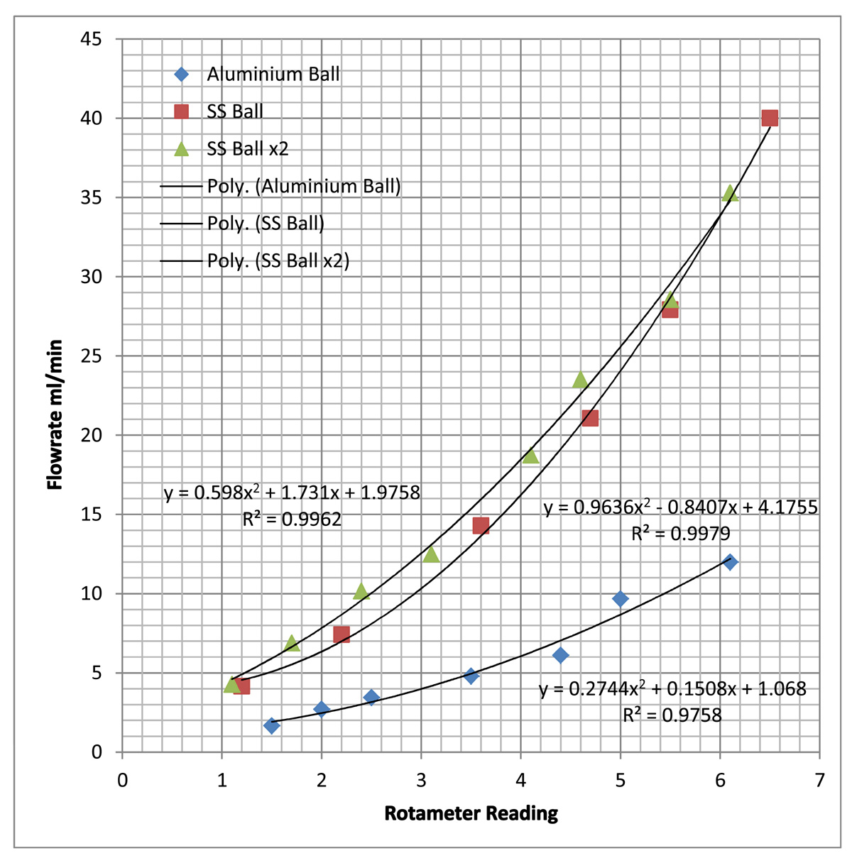
This is one of the simplest procedures to alter the flow range. The plots to the right show the calibration curves obtained using an Aluminium float 0.125 inch in diameter, a single 316 stainless steel float of the same diameter, and two stainless steel floats each 0.125 inch in diameter.
As expected the aluminium float gives a calibration plot with the lowest full-scale flow rate, while the stainless steel float results in a higher range of flow rates being measurable. The slopes of the plots are proportional to the density of the float material.
The effect of inserting a second float of the same diameter into the rotameter tube, has no significant effect on the calibration plot. This is indubitably because two floats of the same diameter very close to each other in the same tapered rotameter bore will experience the same uplift from the moving fluid. Thus inserting a second float of the same diameter as the first is equivalent to placing two similar rotameters in series.
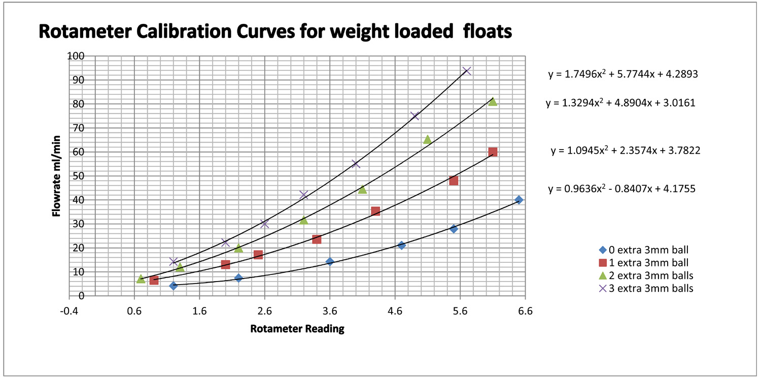
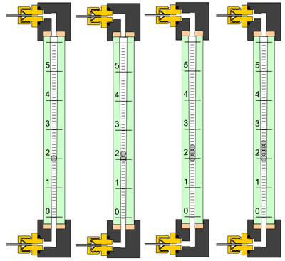
An effective way of changing the rotameter range is to load the float with one or more additional floats which are slightly smaller than the float used for measurement. This method was investigated by adding 3mm stainless steel ball bearings to a rotameter such that the additional ball bearing rested on the original float which, in this case was 1/8 inch in diameter (3.175mm). The calibration results are shown to the left.
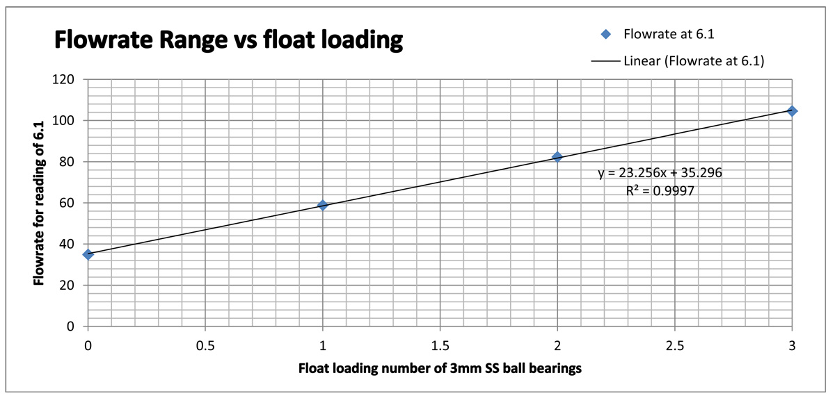
The addition of the extra weights progressively increases the maximum measurable flow rate, linearly with the applied weight as the plot below demonstrates
Changes in flow rate response of a rotameter can be achieved by making small changes to the float diameter but this is accompanied by a reduction in dynamic range. For example if a 3mm ball is used instead of a 1/8 inch ball, the rotameter readings against flow rate are altered according to the following table:
| Rotameter Reading | Flow rate with 1/8 inch(3.175mm) ball | Flow rate with 3mm ball |
| 2.7 | 8.93 | 638 |
| 5.5 | 28.7 | 747 |
| 6.3 | 37.12 | 855 |