
ALL MATERIAL COPYRIGHT KEVIN SCOTT 2011. LINKS TO THIS SITE ARE WELCOME BUT DO NOT COPY MATERIAL FROM THIS SITE TO ANY OTHER WEBPAGE.


If you find this site useful, please support it by making a donation of $1 to help maintain and develop it. Click on the PAYPAL DONATE button to do this safely. But there is no obligation - please avail yourself of the information and facilities of the site at no charge.
The Peltier Cryostat described in these pages can be controlled to enable stable refrigeration temperatures to be maintained at any chose value within the range of which the device is capable. Although the design of custom electronics to do this would be reasonably straightforward, and alternative procedure is to exploit the programmability of the HP 6274B power supply used for testing. The manual for the HP 6274B power supply can be obtained as a pdf from here. In the configuration described here, the voltage control of the current was chosen a the most appropriate mode. In this case, a voltage lying between 0 and 500 mV is applied to two terminals on the rear of the instrument via a 1.5k resistor and the output current is then delivered at a rate of 1 amp per 33.3mV. In practice, this control worked well above about 2 amps but below this was somewhat less stable than could be desired. Nevertheless, it was found that satisfactory control of the cryostat temperature could be obtained from about zero C down to -25 C.
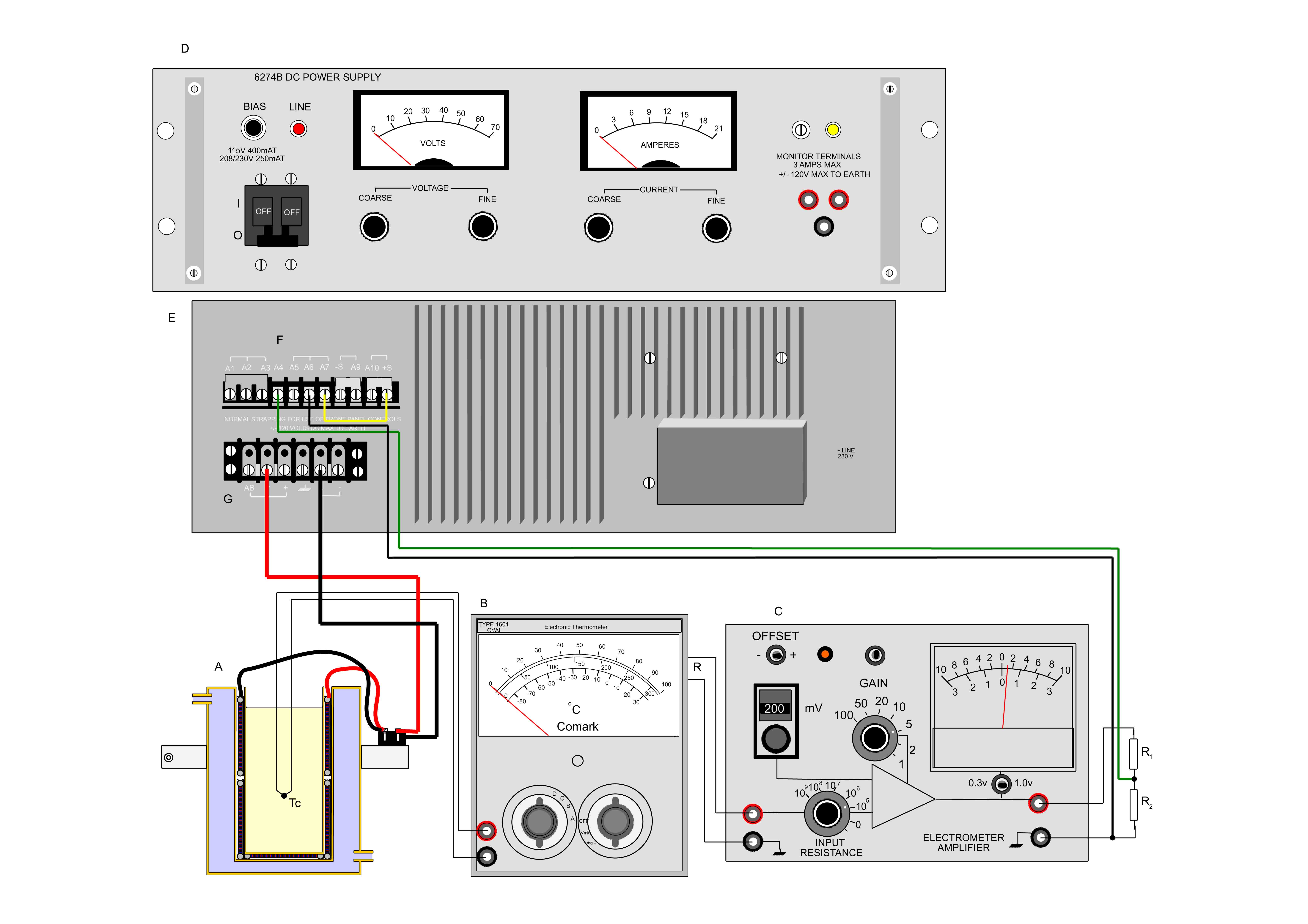
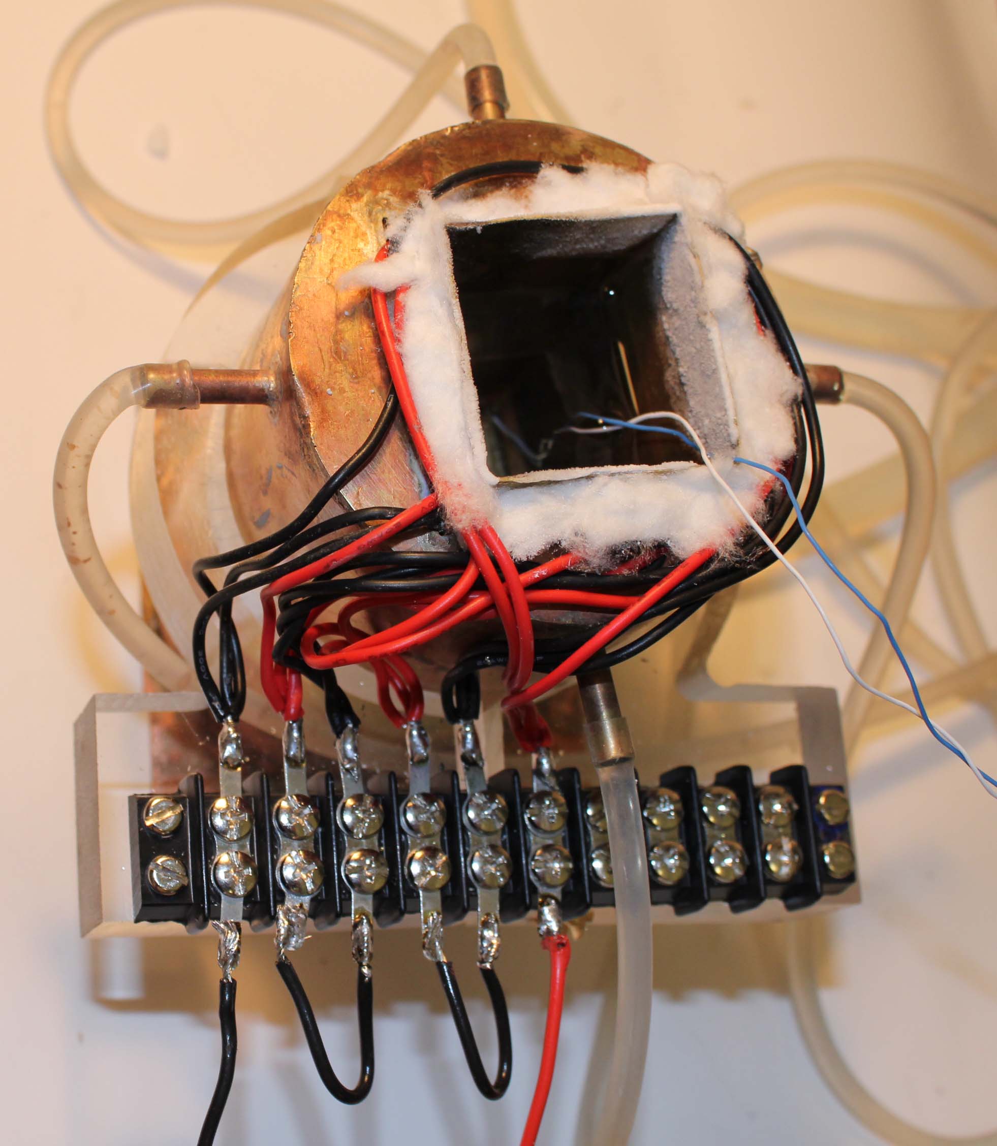
The diagram shows the control system. The cryostat A is provided with a Chromel Alumel thermocouple Tc which is connected to the input terminals of a Comark 1601 electronic thermometer. These analogue instruments are obsolete but still occasionally available and perform excellently. They are equipped with a 1 volt recorder output which, in the case of the 1601 model on range A ( -80 -+20 C) provides a signal of 10mV per degree. This is fed to a differential amplifier C set to a voltage gain of 5. The output of this instrument lay in the range of 0- 2 volts and was attenuated by R1 and R2 to provide a voltage of 0 -500mV. It is important not to exceed 600 mV control voltage into the HP6274B. R1 was 300 ohms and R2 was 100 ohms. The Attenuated voltage was fed to the control input of the power supply via a 1.5K resistor. The output of the supply was taken to the peltier elements in the cryostat.
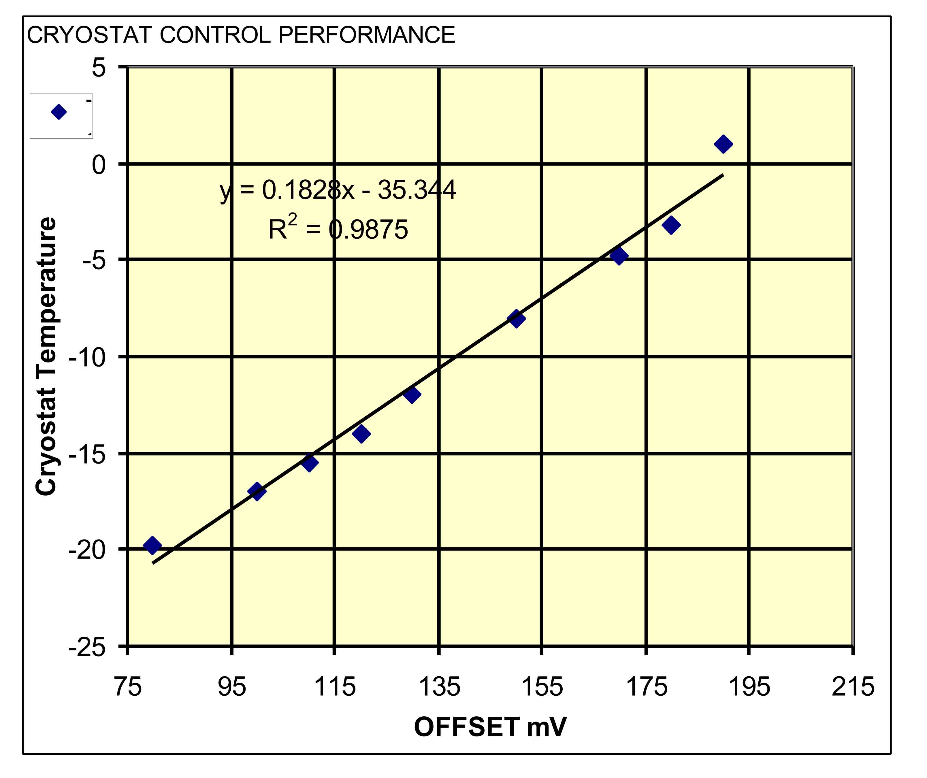
The cryostat was allowed to equilibrate for a series of setting of the offset on the differential amplifier. Table 1 shows the results which are also presented graphically below.
| OFFSET | Tc | Current |
| mV | deg C | amps |
| 190 | 1 | 2.5 |
| 180 | -3.2 | 2.8 |
| 170 | -4.8 | 3 |
| 150 | -8 | 4 |
| 130 | -12 | 5 |
| 120 | -14 | 6 |
| 110 | -15.5 | 6.5 |
| 100 | -17 | 7.5 |
| 80 | -19.8 | 9.1 |
The cryostat responded well when thermal disturbances were applied to it. A test tube of water froze rapidly and the cryostat current increased for a short time to maintain the set temperature. More quantitative estimates of it performance can be obtained by using an electronic microcalorimeter to apply known amounts of heat while the temperature is monitored.
Kevin Scott