ALL MATERIAL COPYRIGHT KEVIN SCOTT 2011. LINKS TO THIS SITE ARE WELCOME BUT DO NOT COPY MATERIAL FROM THIS SITE TO ANY OTHER WEBPAGE.


If you find this site useful, please support it by making a donation of $1 to help maintain and develop it. Click on the PAYPAL DONATE button to do this safely. But there is no obligation - please avail yourself of the information and facilities of the site at no charge.
In order to measure the magnetic field strengths, a simple gauss meter was constructed using the Texas
Instruments TL173C Hall effect gauss sensor. These sensors exploit the phenomenon known as the Hall effect
in which a steady current flowing through a conductor in a magnetic field, causes an EMF to develop at
right angles both to the current and to the field. By using certain semiconductors to carry the current
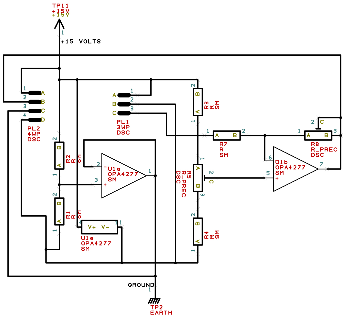
this EMF can be maximised and used for measurement of the field. Referring to the schematic, U1a splits the 12 V power supply
while U1b provides voltage gain. The trimmer R5 sets the zero. Output to meter or recorder is via
pin 2 of Pl2. Pins 1 & 4 are 0 & +12 V. Pin 3 is ground, R1,R2 =10K, R3,R4 = 10K, R5 =2K, R7 = 2K2, R8 = 5K, U1 = OPA4277
Pl1 connects to Texas Instruments gauss sensor type TL173C. A = Vcc, B = Ground, C = output.
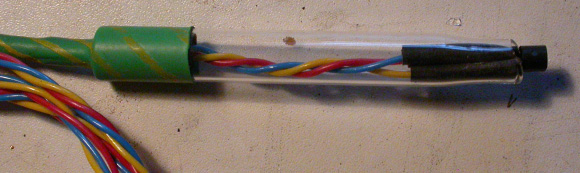
 The TL173C sensor was mounted in a glass holder to form a convenient probe.