
ALL MATERIAL COPYRIGHT KEVIN SCOTT 2011. LINKS TO THIS SITE ARE WELCOME BUT DO NOT COPY MATERIAL FROM THIS SITE TO ANY OTHER WEBPAGE.


If you find this site useful, please support it by making a donation of $1 to help maintain and develop it. Click on the PAYPAL DONATE button to do this safely. But there is no obligation - please avail yourself of the information and facilities of the site at no charge.
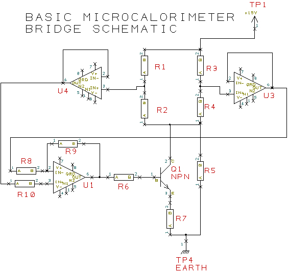
The schematic above shows the basic microcalorimetric system. It consists of a bridge, R1, R2, R3, R4 supplied from a 15 volt rail, the current through the bridge being controlled by transistor Q1. R3, & R4 are reference resistors, R1 is the heater resistor and R2 is a standard resistor. R4 is a coil of wire of a metal or alloy with a reasonably high temperature coefficient of resistance. Some suitable wires are listed in the table below.
| Metal | resistivity | coefficient of resistance | max temperature |
| microhm.cm | 1/K° | °C | |
| Nickel | 6.8 | 0.006 | ~1000 |
| Monel 400 | 48.2 | 0.0011 | 400 |
| Stainless Steel 316 | 49.6 | 0.001 | 900 |
Correctly configured the microcalorimeter system can function as a programmable thermostat while simultaneously measuring
power dissipation. It can thus be used for differential thermal analysis, for measuring specific heats,
latent heats of fusion and evaporation, as well as heat losses though insulation materials. The thermal transfer through
silvered and non-silvered vacuum jackets has been determined using the system. (details here.
The author has also used
the system for measuring the thermochemistry of the hydrogenolysis of aliphatic aldehydes on a Nickel catalyst.
See Journal of The Chemical Society, Faraday Transactions 1, 1978, Vol. 74.
(Download pdf here)
The main application dealt with here, however is the use of the microcalorimetric system as a precision temperature
controller. Apart from the obvious feature that the power supplied to the heater is directly monitorable, the use of the
heater filament itself as the temperature sensor simplifies the heater construction greatly and is a considerable
advantage where wiring has to be kept to a minimum, for example in vacuum systems with limited numbers of lead-throughs.
With the addition of computer control, a wealth of data can be derived from this heating system and used to provide
sophisticated heating and cooling programmes. If the operational amplifiers are fast, the circuit is capable of providing very rapid
heat pulses with no risk of burning out the filament.
The schematic for a microcalorimetric temperature controller is shown below: If it is difficult to read, a pdf can be downloaded here
.jpg)
The circuit is a more elaborate version of the one at the top of this page. R18 is a high wattage precision 2 ohm standard resistor from Rhopoint and is fitted with a heatsink. The heater itself is not shown but is connected between PL4 and the 15V 5amp supply. The remaining bridge resistors comprise R66 and digital potentiometer U29 and resistors selected from the arrays attached to CONN2 and CONN6. This latter arrangement allows selection to be made for coarse temperature range and for allowance for variation of cold heater resistance. The bridge outputs are buffered by operational amplifiers U1a and U1b and applied to the differential amplifier U18a which drives the bridge current controller Q11. Amplifiers U18b, U18c, and U18d gather heater voltage and current data and feed these to the 12 bit A/D converter U17. This can be addressed by the microcontroller via the latch U16, which also controls the digital potentiometer U29. The circuit is capable of maintaining the heater at a particular temperature until addressed by the micro-controller with fresh instructions.