
ALL MATERIAL COPYRIGHT KEVIN SCOTT 2011. LINKS TO THIS SITE ARE WELCOME BUT DO NOT COPY MATERIAL FROM THIS SITE TO ANY OTHER WEBPAGE.
If you find this site useful, please support it by making a donation of $1 to help maintain and develop it. Click on the PAYPAL DONATE button to do this safely. But there is no obligation - please avail yourself of the information and facilities of the site at no charge.
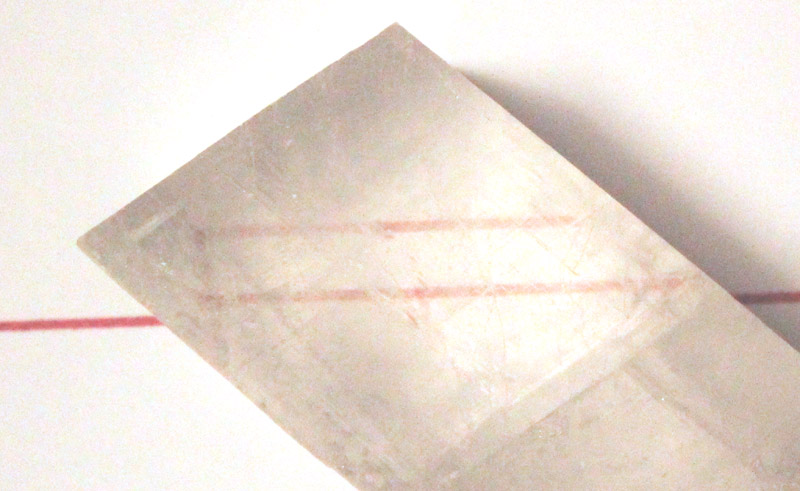
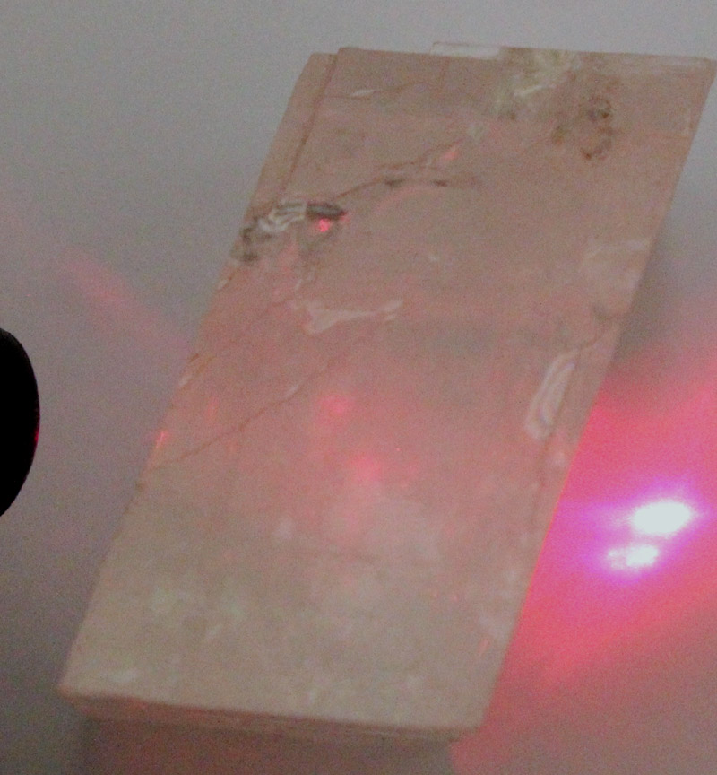
When a beam of light impinges on a calcite crystal, the ray is split into an ordinary ray and an extra-ordinary ray. This is because the crystal in anistropic, having optical properties which differ according to the direction the ray takes in the crystal. This phenomenon is illustrated in the plates above: on the left, a beam of light from a laser is clearly split into two in its passage through the crystal, and on the right, a ruled red line on paper under the crystal produces two parallel lines to the observer's eye.
The ordinary ray lies in the plane of the incident ray and the normal and obeys Snell's law and towards it the crystal behaves as an isotropic solid like glass. The extra-ordinary ray generally does not obey Snell's law and does not lie, in the general case, in the plane of the incident ray and normal.
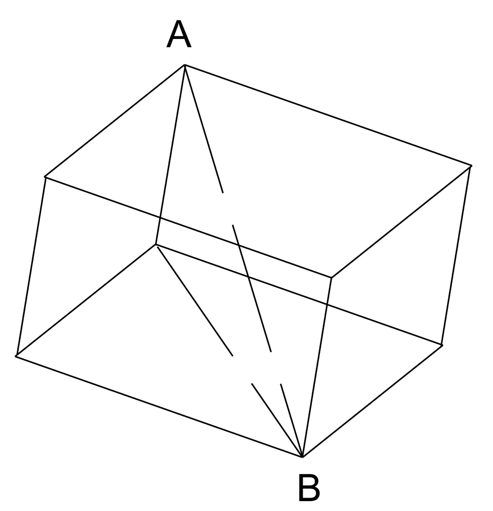
Consider a crystal of Iceland Spar, a very transparent variety of Calcite (CaCO3) as represented by the rhombohedron on the right. Two of the diametrically opposed solid angles are bounded by three plane obtuse angles (101° 55') Hugens found that the results are identical whichever pair of parallel faces of the calcite rhombohedron are used to transmit the light, and hence he concluded that the optical properties are related to directions in the crystal which are symmetrically situated with repect to these planes. In a rhombohedron of equal sides, the only lines having this property are parallell to the single line joining the corners in which the three equal plane obtuse angles meet. A line drawn inside the rhomb so as to make equal angles with the three edges meeting at A or B, or any line parallel to this, is called the optic axis of the crystal, and since Iceland Spar has only one optic axis it is called a uniaxial crystal.
A plane drawn at right angles to the refracting surface of the crystal so as to contain the optic axis, or any plane parallel to this, is called a principal plane of the crystal. It is found that the ordinary ray is polarised parallel to the principal plane of the crystal and the extra-ordinary ray is polarised perpendicular to the principal plane.
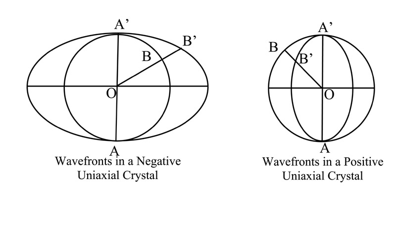
Since the ordinary ray is refracted in the same way as in an isotropic medium, Huygens assumed that it spread as a spherical wave, its wavefront being a sphere. The extraordinary ray, which is not necessarily in the plane of the incident ray and normal, and does not usually obey Snell’s law, he assumed had the next simplest type of wavefront, viz, a spheroid, which is an ellipsoid of revolution formed by rotating an ellipse about one of its axes. The section of the spheroid at right angles to this axis is a circle, that parallel to it is an ellipse. The wavefront in a doubly refracting medium thus usually spreads in two sheets, one a sphere, and the other a spheroid.
In a uniaxial crystal, having one optic axis, the sphere and spheroid touch at two points, the line joining these being the optic axis. Two cases are possible:
(a) the sphere is inside the spheroid; the extraordinary ray travels faster than the ordinary ray, since when the latter from a source O inside the crystal has reached B, the e-ray from O has reached B’, except along the optic axis, when both rays travel equally fast.
(b) the sphere is outside the spheroid; this is the case of a positive uniaxial crystal; the ordinary ray now travels faster than the extraordinary ray, except in the direction of the optic axis, when both rays travel equally fast.
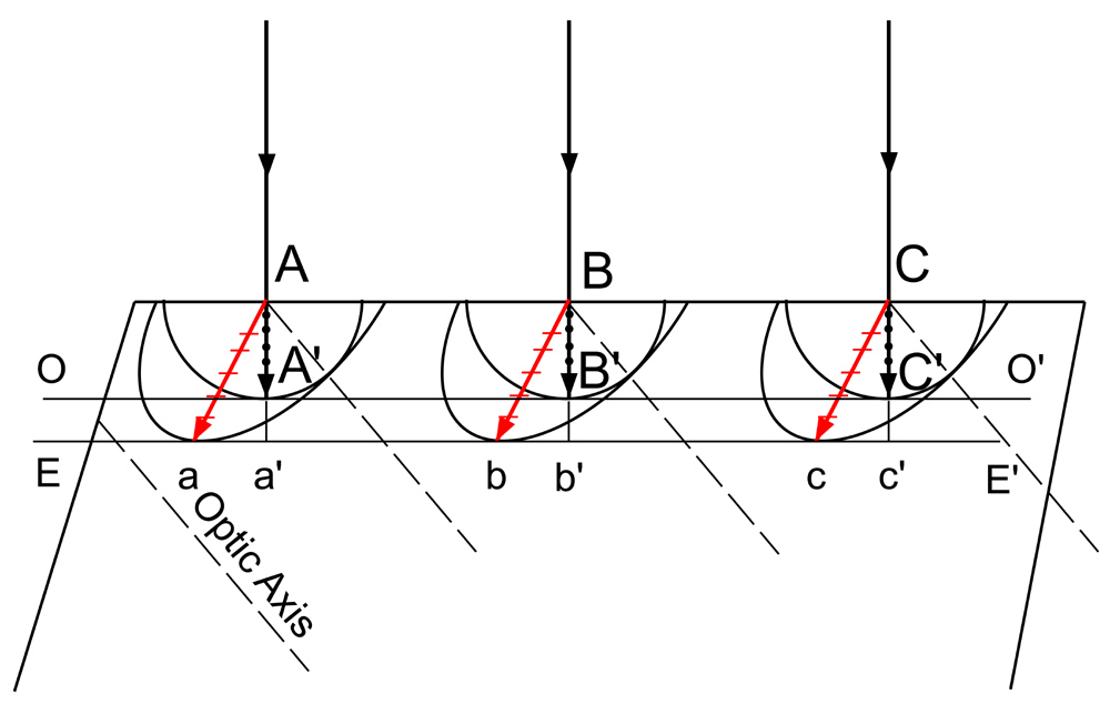
The origin of the double refraction of light at a crystal surface is readily explained in terms of the wave surfaces just described. This is accomplished by the use of Huygens’ principle of secondary wavelets. Consider for example, a beam of parallel light incident normally on the surface of crystal like calcite, whose optic axis makes some arbitrary angle with the crystal surface. In the figure above, the optic axis as the direction shown by the broken lines. According to Huygens’ principle we may now choose points anywhere along the wavefront as a new point sources of light. Here A,B, and C, are chosen just as the wave strikes the crystal boundary. After a short time interval the Huygens wavelets entering the crystal from these points will have the form shown in the about figure.
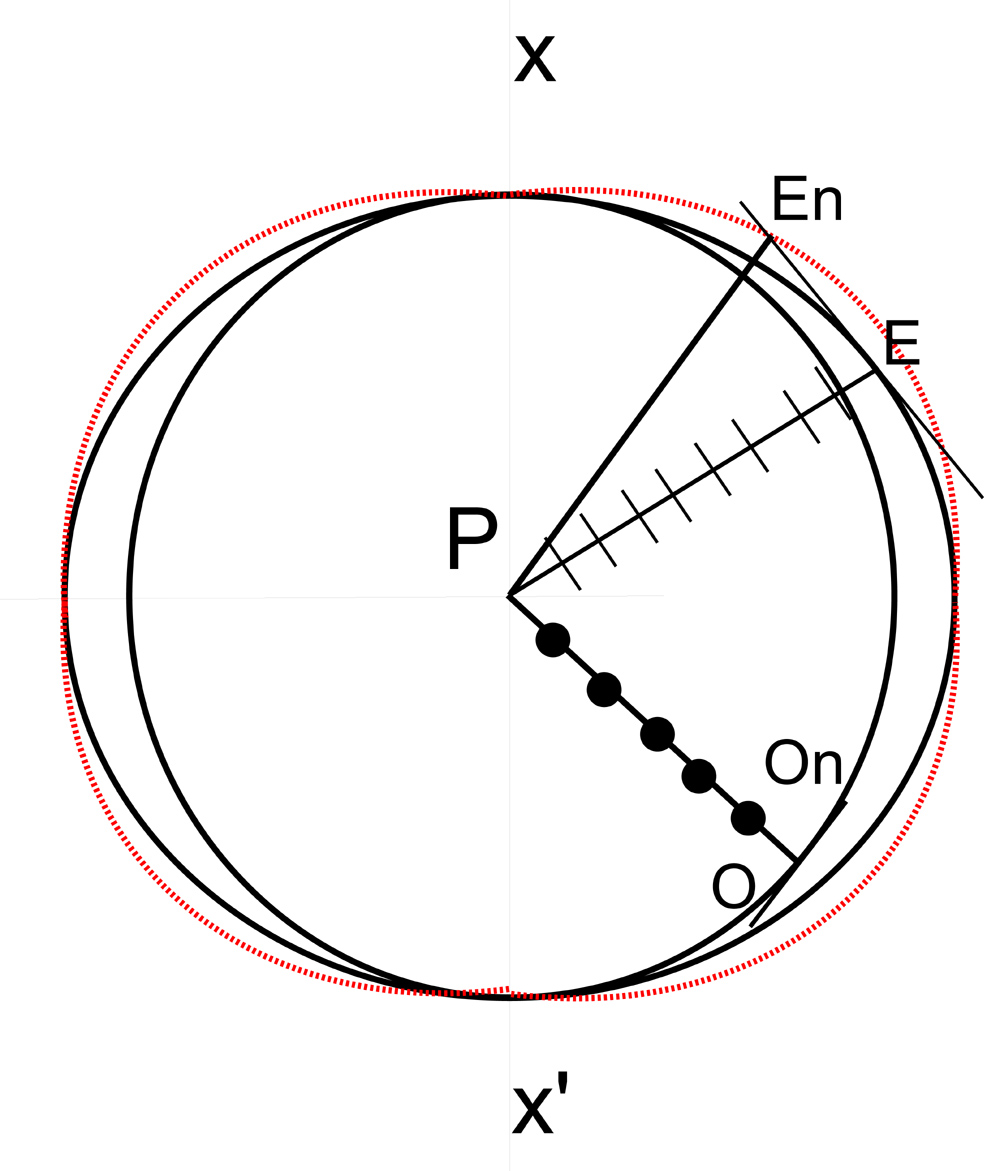
If one now proceeds to find a common tangents to these secondary wavelets, he obtains the two plane waves labelled OO’ and EE’. Since the first is tangent to spherical wavelets, it behaves would a wave in an isotropic substance, travelling perpendicular to the surface with a velocity proportional to AA’, BB’ and CC’. The tangent to the ellipsoidal wavelets represents the wavefront for the E vibrations, which take place in the principal section (the plane containing the optic axis). The E rays, connecting the origins of the wavelets with the points of tangency, diverge from the O rays and are no longer perpendicular to the wavefront. They represent the direction in which a narrow beam of light would be refracted, which is the direction in which the energy of the E vibrations is transmitted. Its velocity, proportional to Aa, Bb, Cc, is called the ray velocity. This is greater than the normal velocity, measured by Aa’, Bb’, Cc’, the velocity with which the wave advances through the crystal in a direction normal to its own plane.
In the figure above, the ellipsoid represents the ray velocity surface, while the normal velocity surface, defined by the three dimensional loci of velocities Aa', Bb', and Cc', takes the form of an oval of revolution shown in red in the diagram below, right:
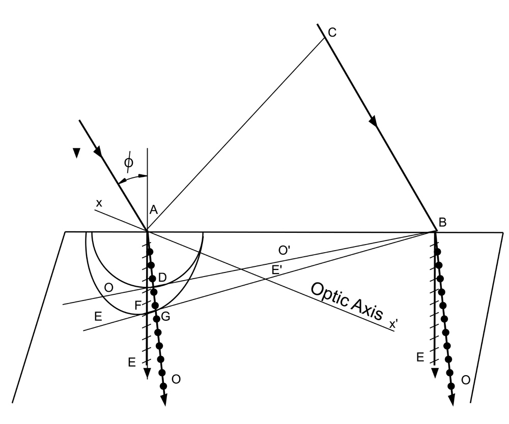
Consider the case of a beam of parallel light incident at an angle on the surface of the crystal whose optic axis lies in the plane of incidence and at the same time makes an arbitrary angle with the crystal surface. See above, left. At the point A where the light first strikes the boundary, the O-wave surface is drawn with such a radius that the ratio CB/AD is equal to the refractive index of the O-ray. The ellipsoidal wave surface is then drawn tangent to the circle at the intersection with the optic axis xx’. The points D and F and the new wavefronts DB and FB are located by drawing tangents from the common point B to the circle and ellipse. While the light is travelling from C to B in air, the O vibrations travel from A to D in the crystal and the E vibrations travel from A to F.
In negative crystals, such as calcite, the principal index for the extraordinary wave is defined as the velocity of light in vacuo divided by the maximum velocity in the crystal.
In positive uniaxial crystals the principal index for the extraordinary wave is defined as the velocity of light in vacuo divided by the minimum velocity of the E wave.
The principal indices for uniaxial crystals are readily determined experimentally by refracting light through a prism of known angle. the refractive index is given by:
n = (sin½(α+δm))/sin½α
where δm is the angle of minimum deviation and α is the angle of the prism. Some refractive indices of uniaxial crystals are given in the the table below:
| Substance | ω | ε |
| Cinnabar HgS | 2.8189 | 3.1461 |
| Rutile TiO2 | 2.6158 | 2.9029 |
| Calomel Hg2Cl2 | 1.9733 | 2.6559 |
| Zircon ZrSiO4 | 1.9313 | 1.9931 |
| Brucite Mg(OH)2 | 1.560 | 1.581 |
| Quartz SiO2 | 1.5442 | 1.5534 |
| Urea CO(NH2)2 | 1.484 | 1.602 |
| Ice H2O | 1.3091 | 1.3104 |
| Substance | ω | ε |
| Haematite Fe2O3 | 3.22 | 2.94 |
| Anatase TiO2 | 2.5354 | 2.4959 |
| Siderite FeCO3 | 1.8728 | 1.6326 |
| Corundum Al2O3 | 1.7690 | 1.7598 |
| Magnesite MgCO3 | 1.7102 | 1.5158 |
| Calcite CaCO3 | 1.6584 | 1.4864 |
| Apatite Ca5(PO4)3F | 1.6388 | 1.6346 |
| Sodium Nitrate NaNO3 | 1.5853 | 1.3358 |
| Ammonium Arsenate (NH4H2AsO4 | 1.5766 | 1.5271 |
| Beryl Be3Al2(SiO3)6 | 1.5740 | 1.5690 |
| Potassium Arsenate KH2AsO4 | 1.5674 | 1.5179 |
| Nickel Sulphate NiSO4.7H2O | 1.5109 | 1.4873 |
| Potassium Phosphate KH2PO4 | 1.5095 | 1.4648 |
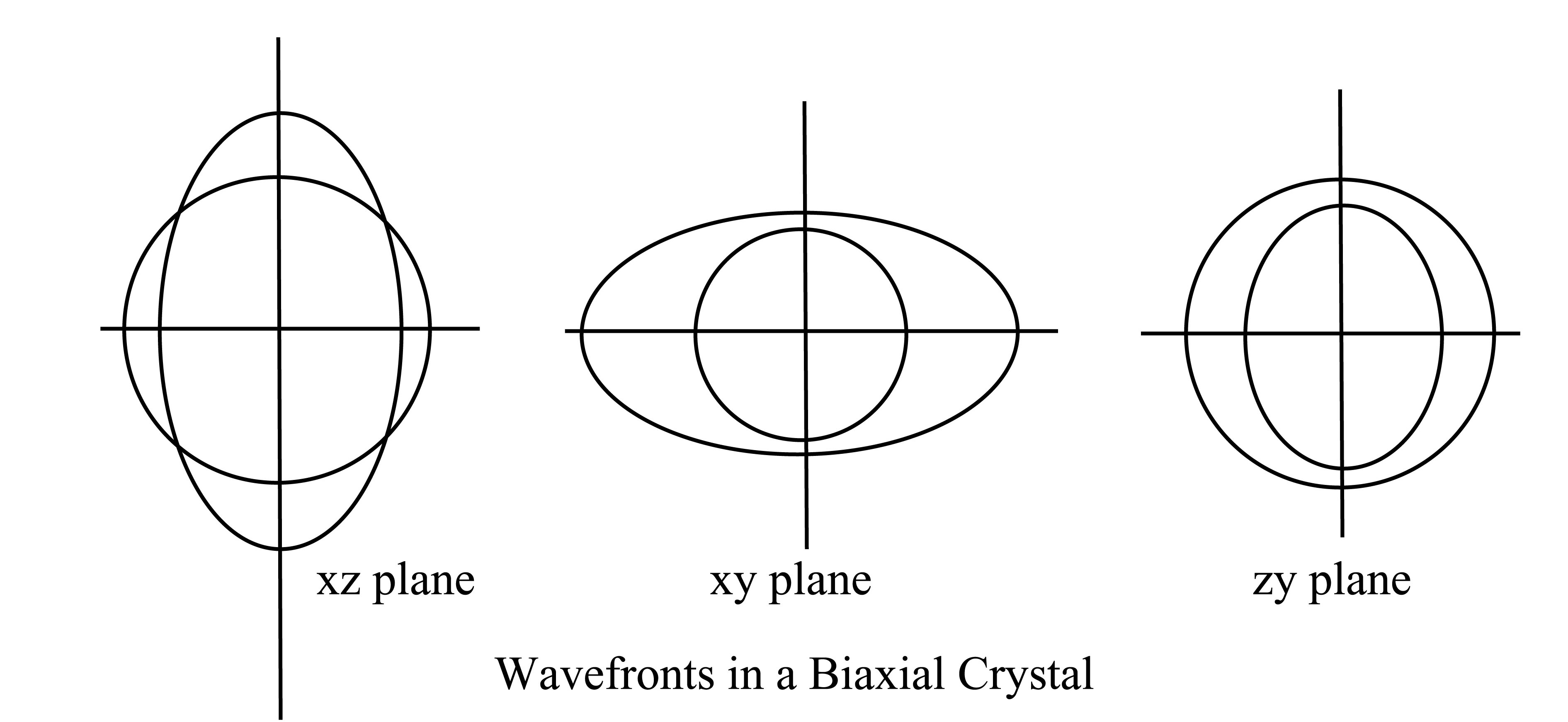
The majority of crystals occurring in nature are biaxial, possessing two optic axes, or directions of single normal velocity. Double refraction in such crystals, just as in calcite and quartz, is most easily described in terms of wave surface diagrams and Huygen's principle. Three cross-sectional views of the wave surfaces for a biaxial crystal are shown above. Each section cuts the two surfaces in one circle and one ellipse and these are different in the three sections.
Of the three cross sections, the left hand one (that is in the xz plane) is the most interesting, for it contains the four singular points where the outer wave surface touches the inner surface. As shown in the diagram below the rays OR1 and OR2 represent directions in which there is but one ray velocity. These are not the optic axes. The optic axes are located by drawing tangent planes A1M1 and A2M2. It is difficult to show in two dimensions that these tangent planes Touch the three-dimensional outer surface in circles whose diameters are A1M1 and A2M2, but such is the case. Since the cross-section of one surface is a circle the lines OA1 and OA2 are perpendicular to the tangent planes. They therefore give the same normal velocity for both the ellipse and the circle, so that OA1 and OA2 are the optic axes for the point O.
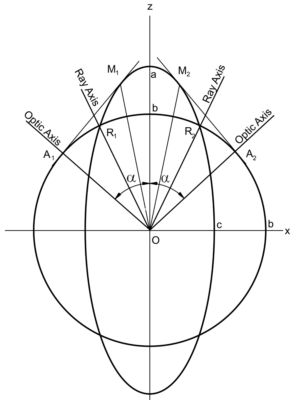
From the waves surfaces above, it may be seen that one can determine the shape of the wave surfaces by specifying three principal indices of refraction. These are determined by the fact that there are three particular velocities, corresponding to vibrations parallel to x, y, and z, respectively. If the wave surfaces represent the wavefronts after they have travelled a time of one second from the point O, the indices are given by:
na=V/a; nb=V/b; nc=V/c;
Where V is the distance that light travels in one second in vacuum, and a, b, and c, are the semi-axes of the elliptic sections of the wavefront. Values of na, nb and ncare given for several biaxial crystals in the table below:
| Substance | na | nb | nc | Angle between axes 2α |
| Mica KH2Al3(SO4)3 | 1.5601 | 1.5936 | 1.5977 | 138° |
| Aragonite CaCO3 | 1.531 | 1.682 | 1,686 | 162° |
| Stibnite Sb2S3 λ7620 | 3.194 | 4.046 | 4.303 | 133° |
| Sulphur S | 1.950 | 2.043 | 2.240 | 69° |
| Topaz (2AlO)FSiO2 | 1.619 | 1.620 | 1.627 | 65° |
| Turquoise CuO.3Al2O32P2O59H2O | 1.520 | 1.523 | 1.530 | 40° |
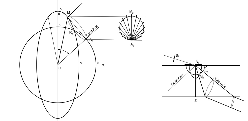
The investigation of refraction in biaxial crystals in the x,z plane is shown in the diagram above where Huygens’ construction using secondary wavelets is depicted. Two special cases arise, however, in which the behaviour of a biaxial crystal is different from the simpler uniaxial type. They correspond to the singular case where light is sent along the optic axis of a uniaxial crystal. One of these, internal conical refraction, is observed when a beam is directed along one of the optic axes inside the crystal. In the other, external conical refraction, it is sent along one of the ray axes.
The diagram below illustrates the phenomenon of internal clinical refraction. Tangent plane A2M2 makes contact with the three-dimensional wave surface in a circle of diameter A2. Suppose now that a plane parallel plate is cut from a crystal so that its surfaces are perpendicular to an optic axis and that the crystal has the thickness OA2. Let a ray of unpolarised light be incident normal on the first surface at O. The perpendicular vibrations Will travel along the optic axis OA2 and pass through undeviated. The parallel vibrations will be propagated along OM2 and will emerge after a second refraction travelling in the same direction as OA2. Now the incident unpolarised ray contains vibrations in all planes through the ray and for each particular plane of vibration there is a different direction along which the wave will be propagated with the same normal velocity as along any other ray. In three dimensions these rays will form a cone of light in the crystal spreading out from O. Arriving simultaneously at the second surface A2M2 all these waves are refracted parallel to each other to form a circular cylinder.
For the demonstration on this page a slide was prepared by heating a microscope slide on a hotplate to 330°C and melting a little Sodium Nitrate on to its surface. The melt was covered with a coverslip which was held down tightly on to the slide while it cooled, until the salt crystallised. The slide was then examined under the microscope using a x10 objective and a x6 eyepiece. Photomicrographs were produced using a Nikon Coolpix 4500 camera attached to the eyepiece using a machined adapter supplied by Brunel Microscopes Ltd.
Figure 1, in the right-hand column, shows the Sodium Nitrate crystals illuminated with non-polarised light. Figure 2 shows the same crystals between crossed-nicol prisms, and the remaining photographs shows the sample between cross-nicol prisms and with a full wave quartz red tint filter interposed between the objective and analyser at different angular positions of the stage. The movie below shows the result of rotating the stage through 360°.
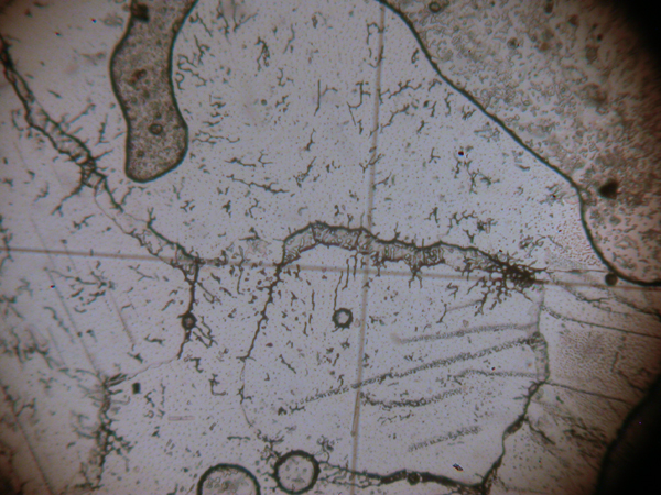
Figure 1. Sodium Nitrate crystalised from the melt viewed with unpolarised light.

Figure 2. Sodium Nitrate crystalised from the melt viewed between crossed nicol prisms.
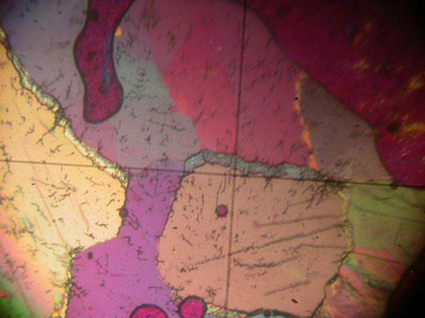
Figure 3. Sodium Nitrate crystalised from the melt viewed between crossed nicol prisms with the addition of a quartz wedge. 0 degrees
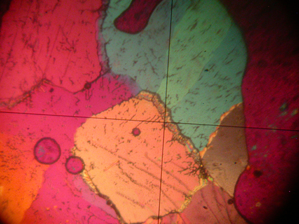
Figure 4. Sodium Nitrate crystalised from the melt viewed between crossed nicol prisms with the addition of a quartz wedge. 45 degrees
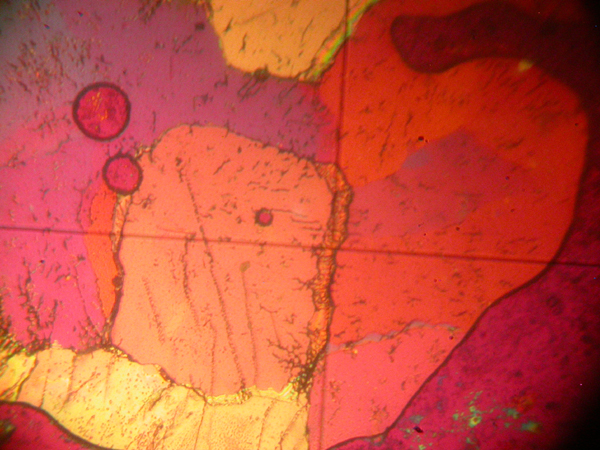
Figure 5. Sodium Nitrate crystalised from the melt viewed between crossed nicol prisms with the addition of a quartz wedge. 90 degrees
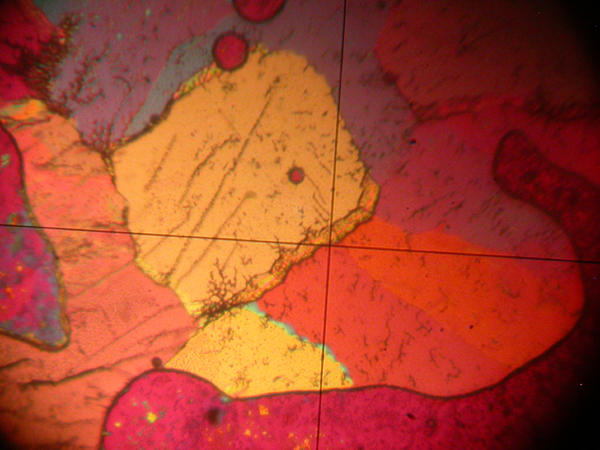
Figure 6. Sodium Nitrate crystalised from the melt viewed between crossed nicol prisms with the addition of a quartz wedge. 135 degrees
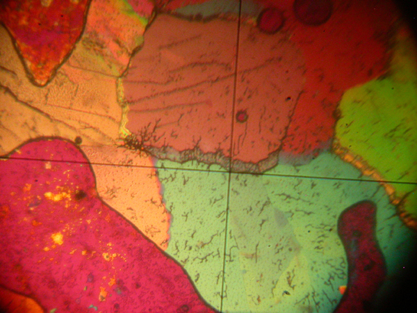
Figure 7. Sodium Nitrate crystalised from the melt viewed between crossed nicol prisms with the addition of a quartz wedge. 180 degrees

Figure 8. Sodium Nitrate crystalised from the melt viewed between crossed nicol prisms with the addition of a quartz wedge. 225 degrees
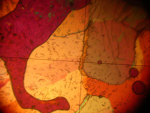
Figure 9. Sodium Nitrate crystalised from the melt viewed between crossed nicol prisms with the addition of a quartz wedge. 270 degrees
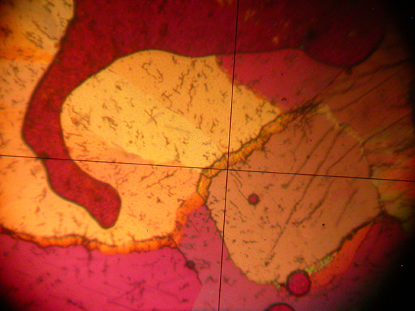
Figure 10. Sodium Nitrate crystalised from the melt viewed between crossed nicol prisms with the addition of a quartz wedge. 315 degrees

Figure 11. Sodium Nitrate crystalised from the melt viewed between crossed nicol prisms with the addition of a quartz wedge. 360 degrees