ALL MATERIAL COPYRIGHT KEVIN SCOTT 2011. LINKS TO THIS SITE ARE WELCOME BUT DO NOT COPY MATERIAL FROM THIS SITE TO ANY OTHER WEBPAGE.


If you find this site useful, please support it by making a donation of $1 to help maintain and develop it. Click on the PAYPAL DONATE button to do this safely. But there is no obligation - please avail yourself of the information and facilities of the site at no charge.
This is an idea. Only a few ideas out of millions yields a seriously effective invention, and there is only a chance that this particular idea will do so. At first sight it may seem improbable, a bit like the inkjet printer. Who would have predicted that an idea involving squirting droplets of different coloured ink from a block by means of electrical heaters could possibly yield a full colour printer with a resolution of 750 dpi?. But that idea did. So against all probability, I embark on the design of a machine to blow square bulbs (or strictly cubical bulbs). This page gives an interim report on the device and suggests the next steps to fulfil its potential.
The mode of operation is simple. A glass bulb is first blown, (ultimately automatically, but initially by hand) on the end of a glass tube mounted in a chuck in a headstock driven by a stepper motor. Propane and oxygen are supplied via electrically operable valves to a burner positioned to heat the bulb. Both the headstock motor and the gas flow valves are controlled by a microcontroller system, with adjustable parameters. With the gas jets supplied with propane and lit, with the oxygen off, the headstock motor is supplied with pulses to turn it through a predetermined angle. In the case of a square section being required, this angle is 90 degrees. After turning the work through this angle, the shaft remains stationary for a determined period (The "dwell period", typically 200 - 500 milliseconds) during which the oxygen supply to the flame is turned on. This makes the flame hot and tends to flatten the glass. At the completion of the dwell period, the oxygen supply is discontinued and the stepper motor rotated through a further angular step. This process continues until a square-section bulb is produced.
Clearly any geometrical cross-section can be generated with appropriate choice of angular step of the motor and asymmetric sections can be produced using the appropriate repeated sequence of angles.
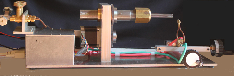
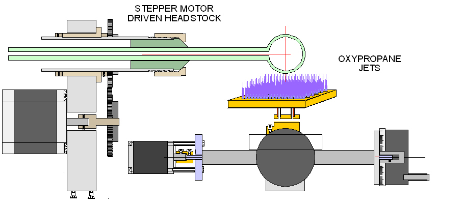
The System schematic is shown below. The headstock consists of a 30mm OD steel tube passing through a bronze bearing 30mm ID, 38mm OD inserted into a aluminium block 120mm x 25mm x 150mm, mounted on an aluminium alloy base plate. A chuck is fashioned at one end of the 300mm tube which is threaded 1mm pitch and carries a brass nut which compresses a collet machined to fit the glass tubing used. The collet is made from FP4 resin filled fibreglass which has sufficient flexibility to clamp the glass firmly without damage and also has reasonable heat resistance.
The burner is supplied with two premixed jets and is mounted upon a positioning table with manual and stepper motor control of the position of the burner in the x and y horizontal directions. The flow of gases to the burner assembly is controlled by two valves constructed in a block of four in a manifold. The other two vales control the supply of air and vacuum to the swivel mounted behind the headstock. Each of these valves is simply constructed from a vertical glass tube 6mm ID mounted between the upper and lower blocks of the manifold. At the lower, outlet end of this tube a 1.6mm OD stainless steel tube projects a few mm into the glass tube and upon it rests an armature consisting of a rod of soft iron 4mm in diameter and 15mm in length having a recessed lower end carrying a rubber insert. This rubber insert is cast in place from a two part mixture of monomer and polymerisation catalyst to form a soft silicone grade Shore 00-01. It was found that if this grade of rubber was used, the weight of the armature was sufficient to close the valve reliably. The 12 volt solenoid fitted over the glass envelope pulls the armature clear of the stainless steel jet when actuated and this allows gas to flow. The valves so constructed were found to be reliable, quiet and fast in their operation.
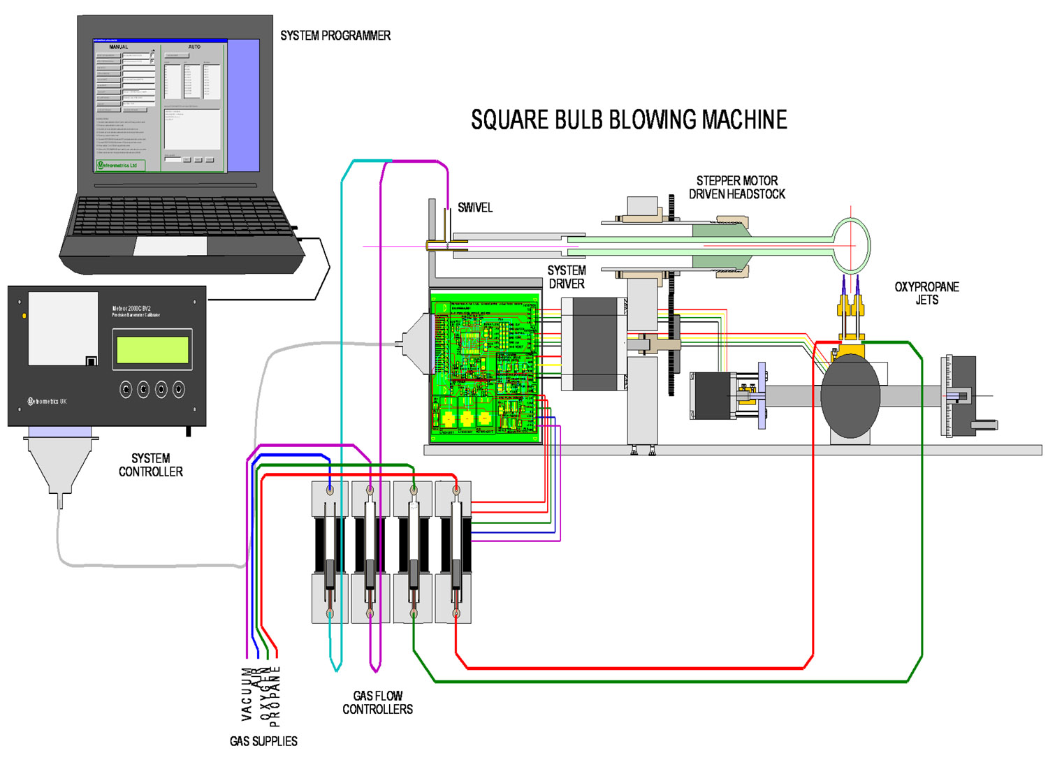
A simple interface board was constructed to actuate the stepper motor and the valve manifold in response to commands sent by the controller. This, in turn, can be programmed and controlled by windows software running on a PC.
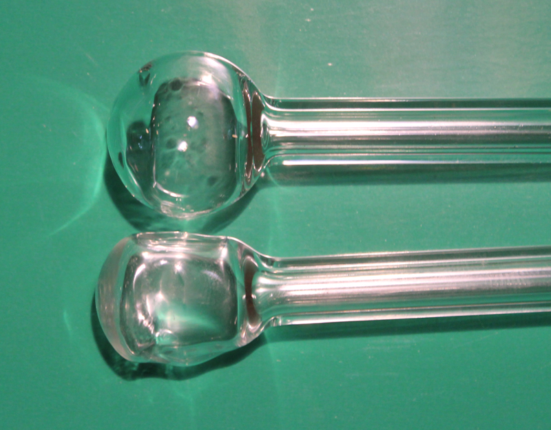
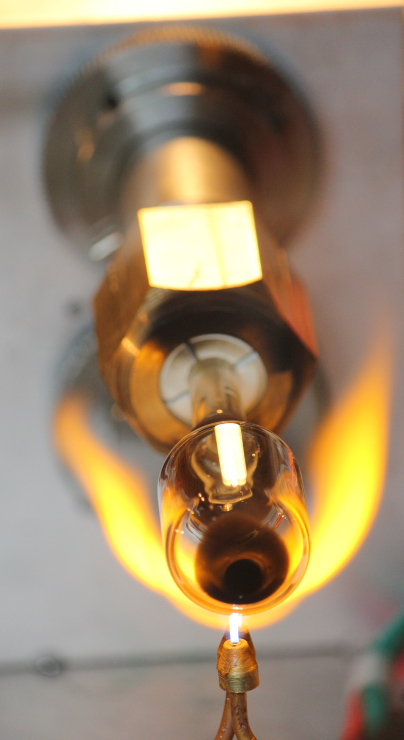
The photograph shows an initial result, which while exhibiting certain rectangular proportions is far from the final objective which has flat uniform faces, sharp edges and equal proportions. The observation of the machine operating suggests some immediate improvements: The twin premixed gas jets produced hot sharp flames but the high temperature was very localised so each face tended to be dimpled. Also, it appeared that there was insufficient heat applied to the work. The solution will be to provide more heat better distributed via surface mixed burners, possibly in a flat grid form as illustrated below.
No use has yet been made of the capacity to provide positive and negative pressures internally in the bulb via the swivel. The use of alternate vacuum and pressure inside the bulb, can flex the flat surface as it is formed thus distributing the glass more uniformly. Also the use of vacuum may sharpen the edges of the geometric shape as it is formed.