ALL MATERIAL COPYRIGHT KEVIN SCOTT 2011. LINKS TO THIS SITE ARE WELCOME BUT DO NOT COPY MATERIAL FROM THIS SITE TO ANY OTHER WEBPAGE.
If you find this site useful, please support it by making a donation of $1 to help maintain and develop it. Click on the PAYPAL DONATE button to do this safely. But there is no obligation - please avail yourself of the information and facilities of the site at no charge.

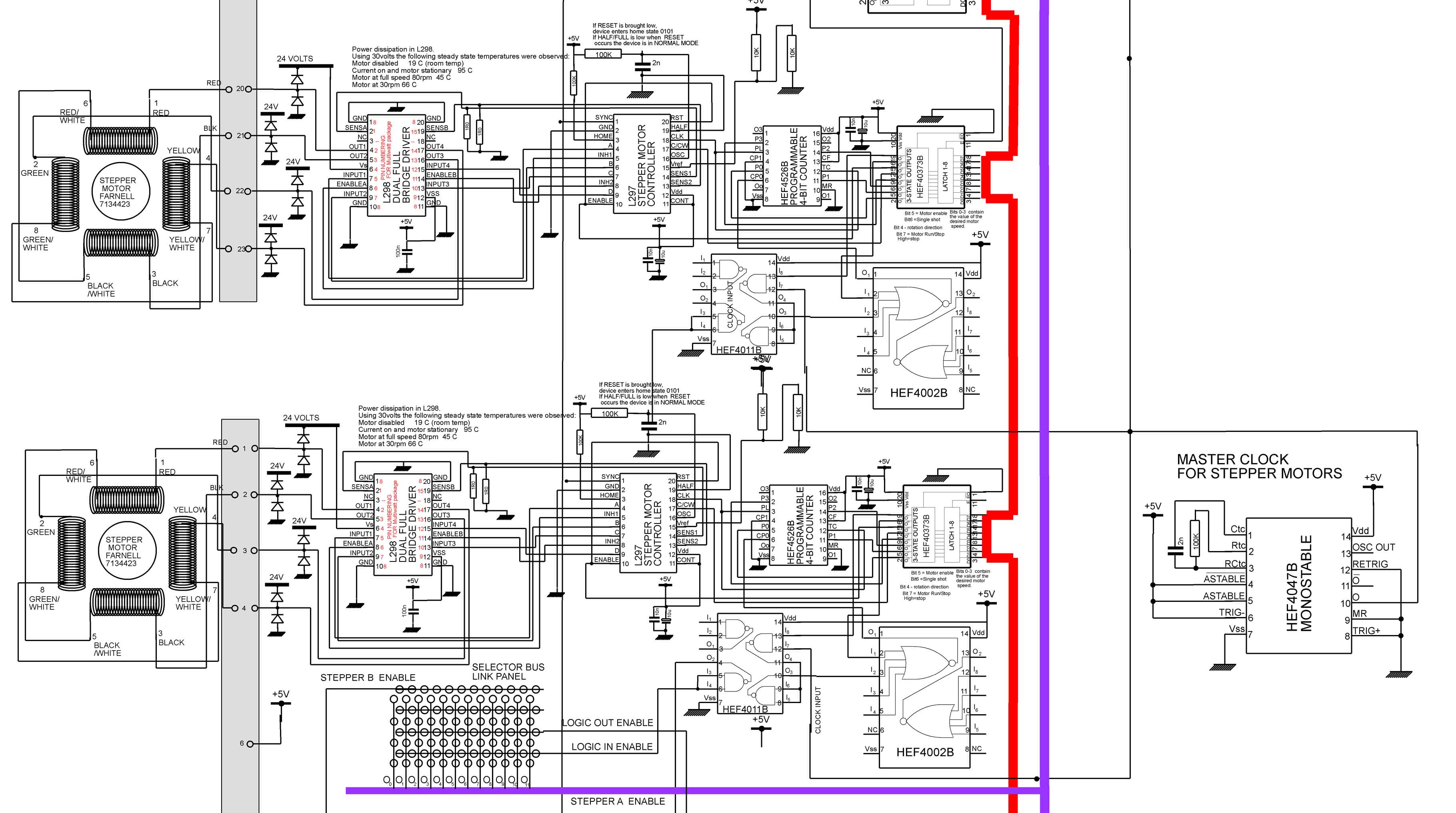
The diagram shows the details of the stepper motor control & drive system. Circuitry for the L298 dual bridge driver is as specified by the chip manufacturer as is the controller circuitry. All the stepper motors are driven by a master clock a HEF4047 in multivibrator mode. The single clock ensures that all motors are synchronised - this being especially important for the headstock and tailstock motors. The controllers are designed to run independently of the processor: once an instruction has been given to a controller via the HEF40373 bidirectional latch, to place a motor in a particular mode, that stepper motor remains in that mode until a fresh instruction is received. With 1 ohm sensing resistors and a 36 volt power supply, The motors gave just sufficient torque at the highest speed (about 150rpm). The L298 dual bridge drivers were attached to heat sinks to prevent over-heating at low motor speeds. From the HEF40373 bidirectional latch, bits 0-3 control the speed of the motors. The contents of these bits are loaded into the parallel inputs of the HEF4526 programmable down counter which is fed with the master clock signal via the gates HEF4011 and HEF4002. Bit 4 of the control input from the bidirectional latch is motor direction, Bit 5 is the motor enable signal, Bit 6 is single shot, Bit 7 is run/stop.