
ALL MATERIAL COPYRIGHT KEVIN SCOTT 2011. LINKS TO THIS SITE ARE WELCOME BUT DO NOT COPY MATERIAL FROM THIS SITE TO ANY OTHER WEBPAGE.


Energy harvesting is the recovery of energy which would be otherwise dissipated in the normal operation of a system and its deployment as a power source. In the example presented in this paper, electronics situated by necessity on a rotating disk are powered by the harvesting of rotational energy from the mechanical movement of the disk. This involves the conversion of rotational kinetic energy into electrical energy, a task accomplished by electromagnetic means. The design presented here only uses standard electronic components for ease and simplicity.
The mechanical layout of the energy harvester is shown on the right. It consists of a disk S driven by motor M and carrying 36 ceramic magnets 6mm long and 4mm in diameter arranged radially at the periphery of the disk. The magnets were pressed into holes drilled in the fibreglass disk S and arranged such that alternate North and South poles were presented uppermost.
An upper disk, carrying inductors was mounted on a perspex frame such that it lay parallel and coaxial with the disk S. The inductors were Bourns, RL622-104K-RC 100mH rated at 0.02A (Farnell 1929727) and were mounted radially at the same radius as the magnets on disk S, but disposed at 40 degree intervals. Up to nine such inductors could be mounted on this disk in this way, but the results described in this paper were obtained with just 5 inductors.
The Inductors were wired in parallel. Unfortunately the direction of the winding was not defined by the component markings so, the correct orientation of each inductor had to be determined before mounting.
For convenience of testing, the magnets were mounted on the rotating disk and the inductors and wiring mounted on the stator disk. This can be reversed when harvested power is required on the rotating component.
The electronics to convert the power gathered from the inductors to a steady DC voltage of 5V and 3.3volts while maintaining a charge on two lithium rechargeable batteries is shown below. A pdf of this circuit can be downloaded here.
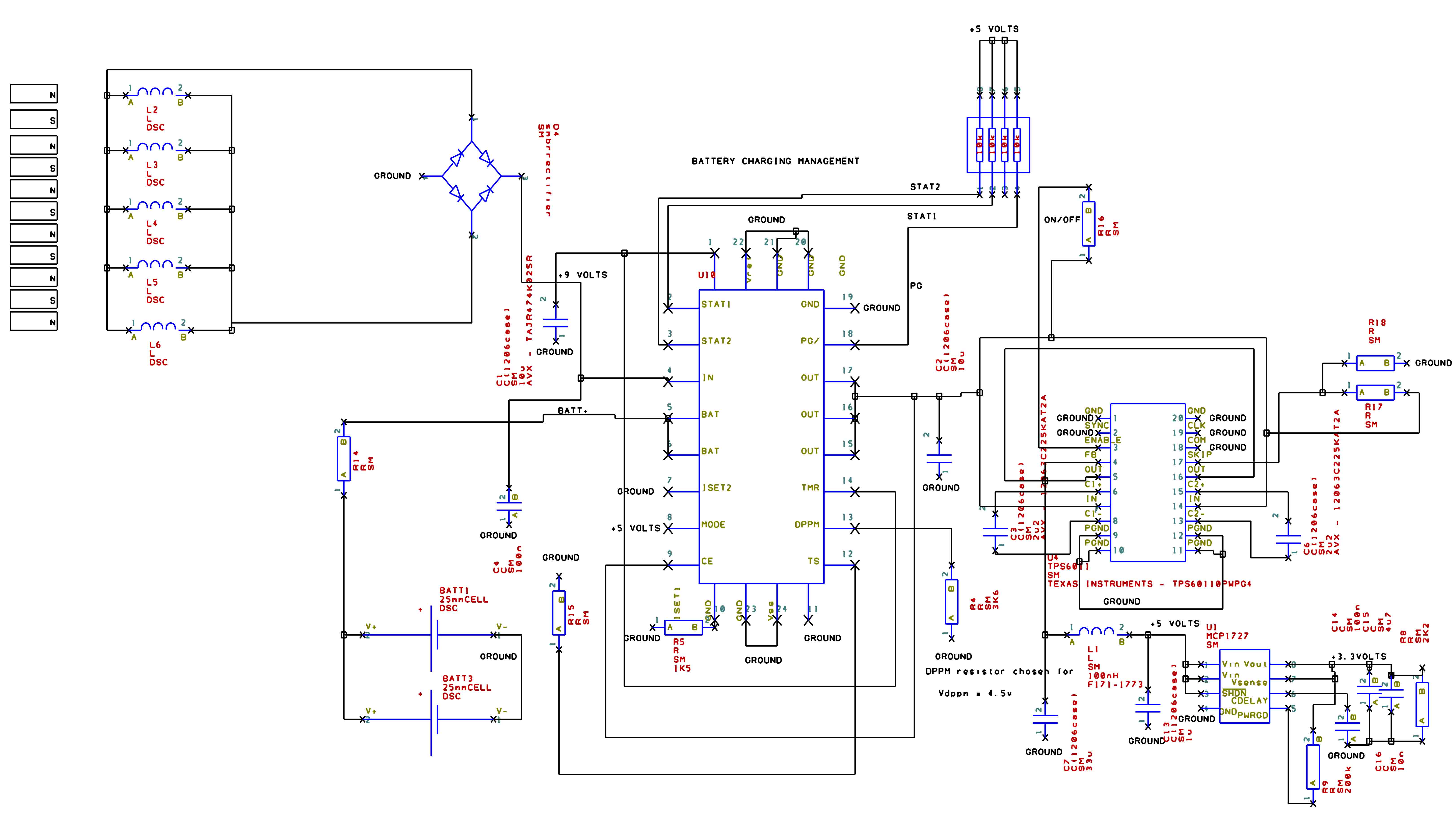
The oscilloscope trace to the lower right shows the raw unloaded voltage obtained from 5 inductors in parallel at about 2500 rpm. The top trace is the signal from an optical tacho sensor on the motor shaft and the lower trace shows the signal from the inductors being 18 times the frequency of the rotation.
The electronics comprises three ICs and their associated components. U18 is a BQ24070 which takes the input power and distributes it to the load and to the Lithium batteries. U4 is a TPS6011 which generates a 5 volt output from a wide range of input voltages, and the MCP1727 provides 3.3volts output. for the tests, the MCP1727 was disconnected by the removal of inductor L1 and all measurements made by loading the 5 volt line.
Initially with a 500 ohm load on the 5volt line, the batteries were allowed to discharge completely with the disk stationary, and then allowed to charge with the disk running at 3000 rpm.The rectified voltage from the inductors, the battery voltage and the 5v line voltage were monitored throughout. The plot is shown on the right.
By varying the load resistance and thus drawing different currents, it was possible to estimate the maximum current which could be drawn under various conditions. This could only be an estimate as the BQ24070 IC regulated the charging conditions to provide a balance between battery charge level and output current. At low output loads, the battery reached full charge while maintaining the output current, at high output loads, the battery subsidised the output which was maintained as long as possible until the battery was exhausted and the output fell to zero. At intermediate loads the charge on the battery was regulated to maximise the power transfer from the energy harvester. This was done by reducing the effective load resistance applied to the inductors to match more closely the output resistance of the energy harvester. Thus the performance was maintained under intermediate load conditions, by automatically adjusting the load impedance to optimise the power transfer.
At first glance it may be thought that the faster the rotational speed the greater the power output, but this is only partially true. The emf generated by the inductors is proportional to the number of magnetic lines of force cut per second, but at higher speeds, there is less time to saturate the inductor cores magnetically. These two effects are antagonistic so, at a separation distance between inductors and the magnet poles of 2.5 mm, the maximum currents drawn from the energy harvester at different rotational speeds are shown in the table:
| MOTOR RPM | Maximum Current mA |
| 3000 | 30 |
| 1500 | 20 |
| 4000 | 30 |
Since the flux from a ceramic magnet falls rapidly with distance away from the pole face, it would be expected that the output from the energy harvester would be greater when the inductor-magnet distance is small. The plot to the right demonstrates this clearly.
The energy harvester described generates audible noise at a frequency 18 times the rotational frequency of the disk. The intensity of the noise generated might be expected to vary inversely with the inductor magnet distance:
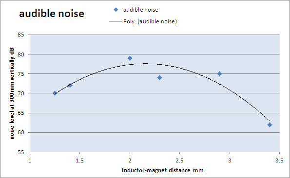
But as the plot shows, the noise level passes through a maximum at about 2.2mm inductor-magnet distance. This may be because at very low distances, the force holding the stator disk in position over the rotating disk is much larger thus clamping and inhibiting the vibration. For very quiet operation, the distance should be larger with a sacrifice of power output.
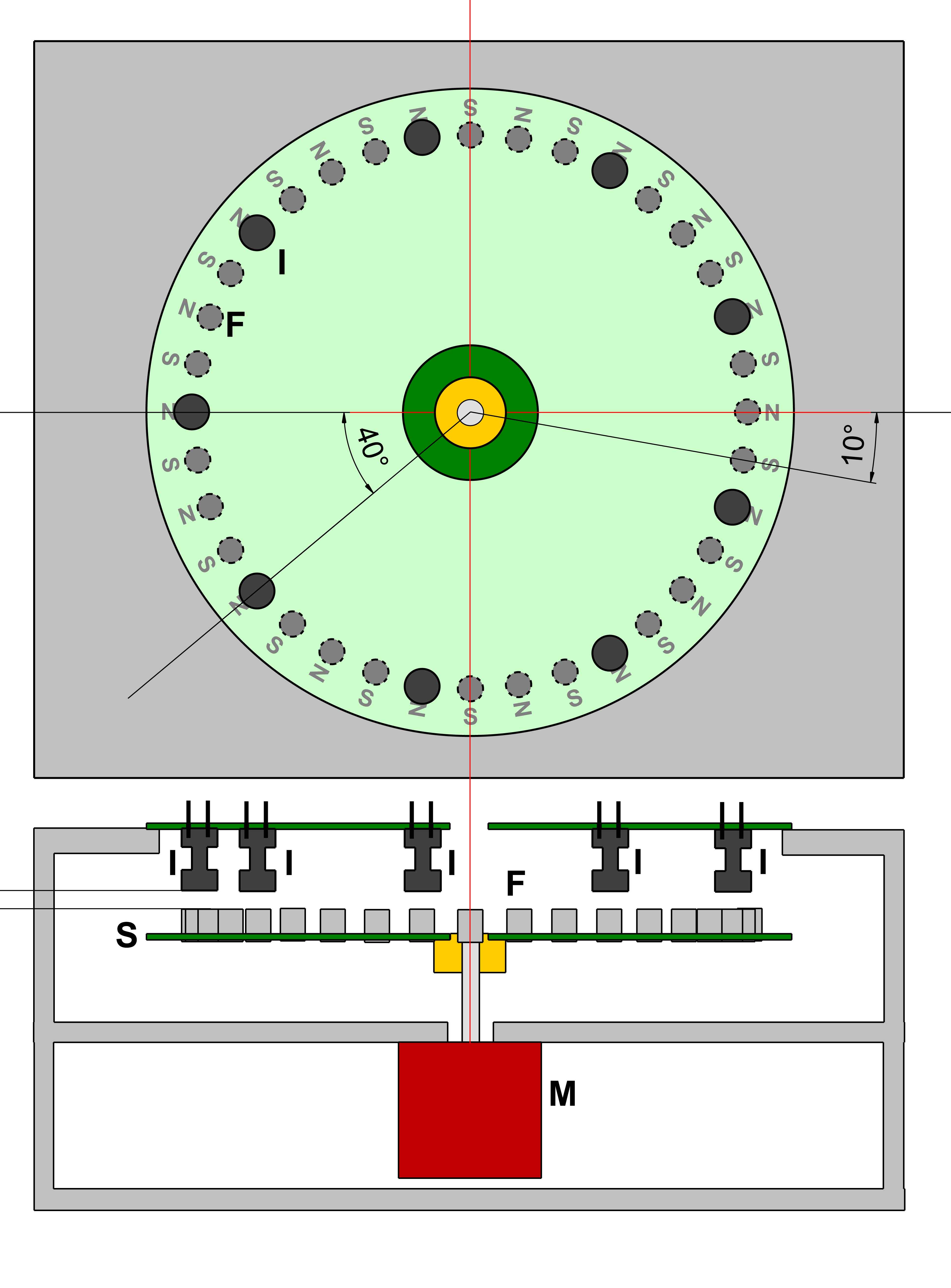
Mechanical construction of the energy harvester
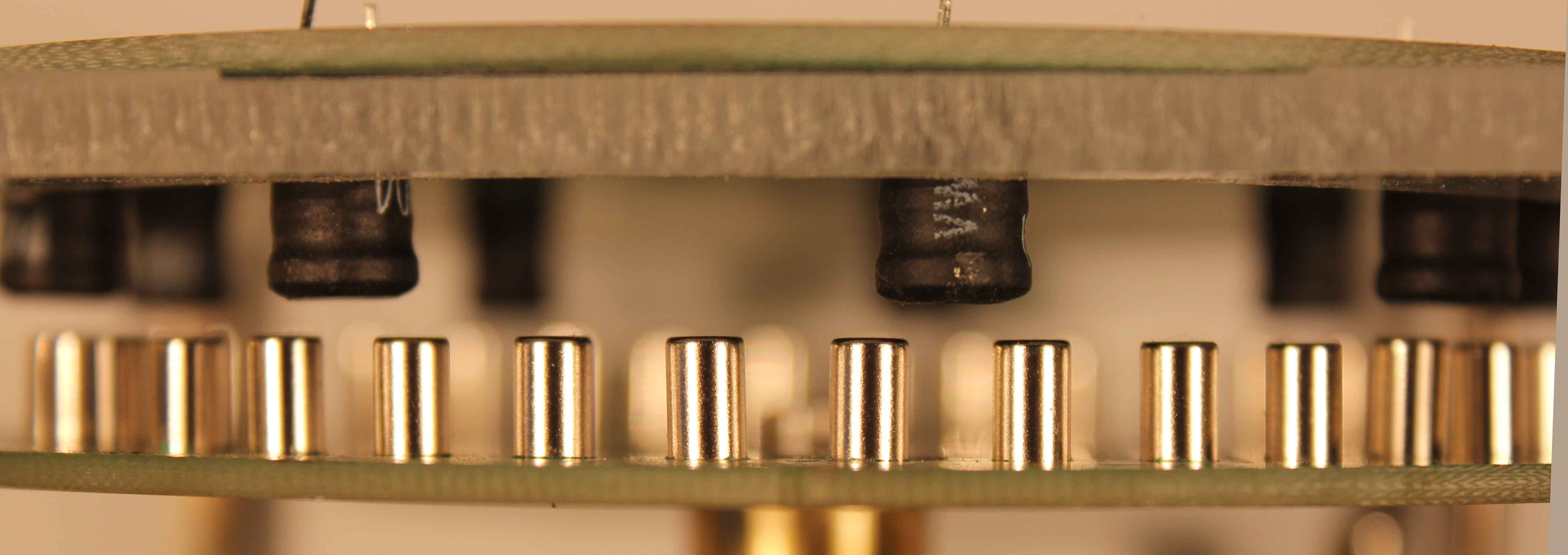
A side view showing inductors and magnets
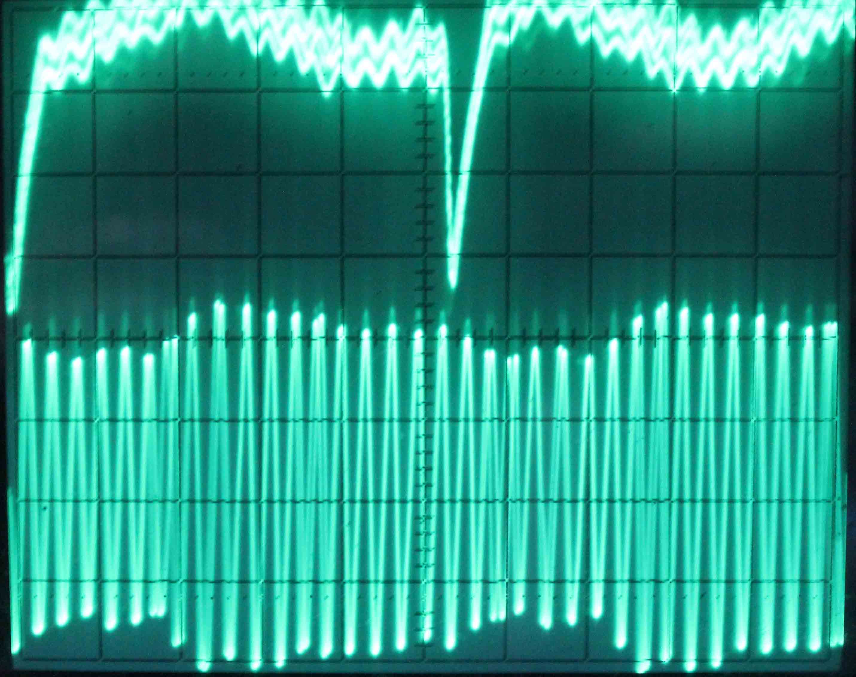
An oscilloscope trace of the inductor output(lower trace), 5ms/division horizontal, 5v/division, vertical.
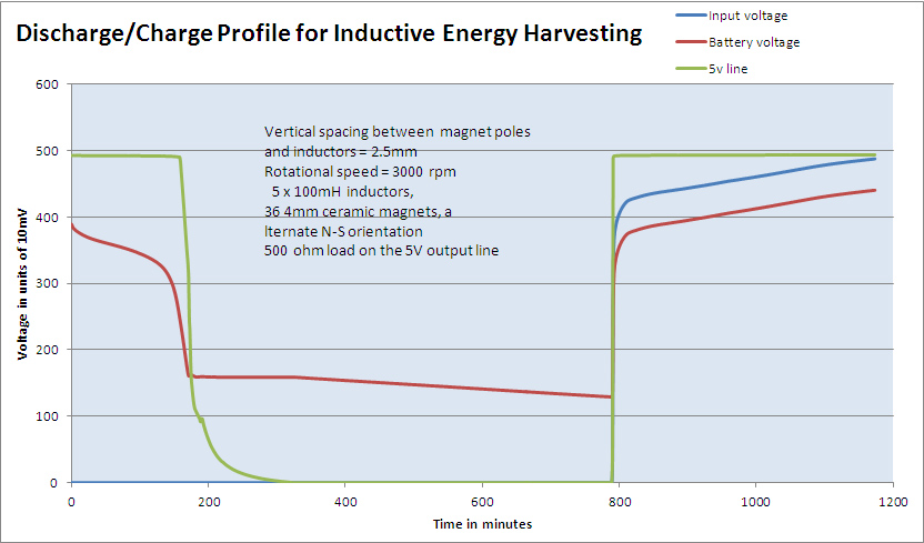
Discharge-charge profile for energy harvester with 500 ohm load
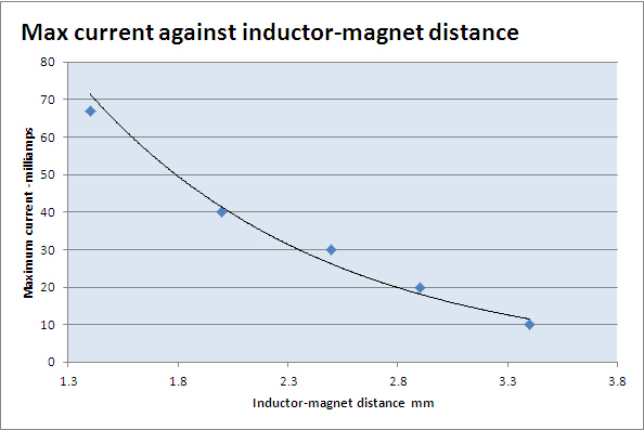
Maximum current against inductor-magnet distance.