
ALL MATERIAL COPYRIGHT KEVIN SCOTT 2011. LINKS TO THIS SITE ARE WELCOME BUT DO NOT COPY MATERIAL FROM THIS SITE TO ANY OTHER WEBPAGE.


If you find this site useful, please support it by making a donation of $1 to help maintain and develop it. Click on the PAYPAL DONATE button to do this safely. But there is no obligation - please avail yourself of the information and facilities of the site at no charge.
An occasion may arise, in the accurate measurement of pressure or volume, when the meniscus of a fluid in a tube needs to be located precisely and automatically. Such detectors may be of two basic types: (a) those that search for a meniscus and determine its position with reference to a fixed point, or (b) those that detect a meniscus passing a fixed point. The device described here is of the latter type. In the particular instance under consideration here, the meniscus needed to be detected with an accuracy of 10 microns or better in relation a fixed point in the instrument.
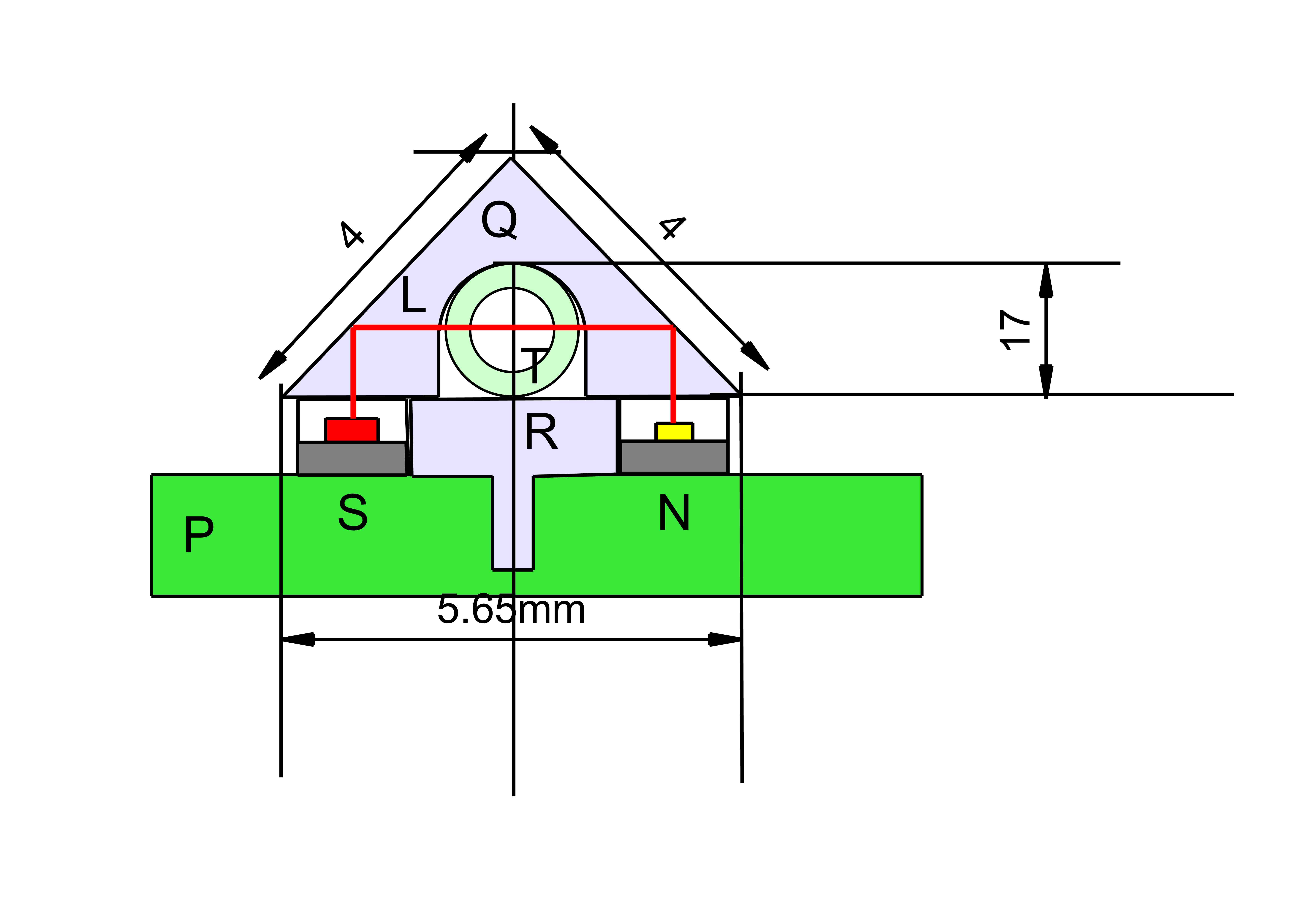
The tube was of borosilicate and 1.6mm OD and 1.0mm ID containing a low-viscosity aviation lubricant ( Aeroshell 3) into which it was permissible to introduce a blue dye. Figure 1 shows the general arrangement. The borosilicate tube T was mounted on an ABS plinth R, on a printed circuit board P and arranged to pass between two 0805 surface mount components: an infra-red light emitting diode ( IR880 High Intensity Series 170 from OSA Opto Light GmbH) S, and an infra-red sensitive NPN phototransistor (Type OP501 from TT Electronics) N. These two components were soldered to the printed circuit board such that their radiating or detecting elements were directed along lines normal to the surface. The emission from the LED and the detection of the phototransistor were constrained within a 100 micron wide slit effected by the use of two strips of adhesive backed aluminium tape separated by 100 microns and secured to both components on their top surfaces. This operation was easily accomplished under a low power microscope fitted with a micrometer. Care was taken to ensure that the slit on the phototransistor was precisely collinear with that on the LED and that the slits were strictly perpendicular to the longitudinal axis of the tube.
An acrylic right-angled prism Q with a slot machined across its hypotenuse provided the optical path L from the LED, through the tube and thence to the phototransistor. It was first thought that such a prism would be expensive to manufacture and polish, but, in fact, a 4mm x4mm x5.65 mm triangular section of acrylic is commercially available and is used as a corner fillet in the construction of acrylic glazed enclosures. It was tested using a laser and found to have a sufficiently polished finish to be optically suitable for this application. A length of this fillet material was machined carefully on a milling machine to provide a rounded slot to accommodate the glass tube. It was found that T-cut polishing compound supplied to polish automobiles, was effective in polishing the walls of the slot to increase sufficiently their optical transparency.
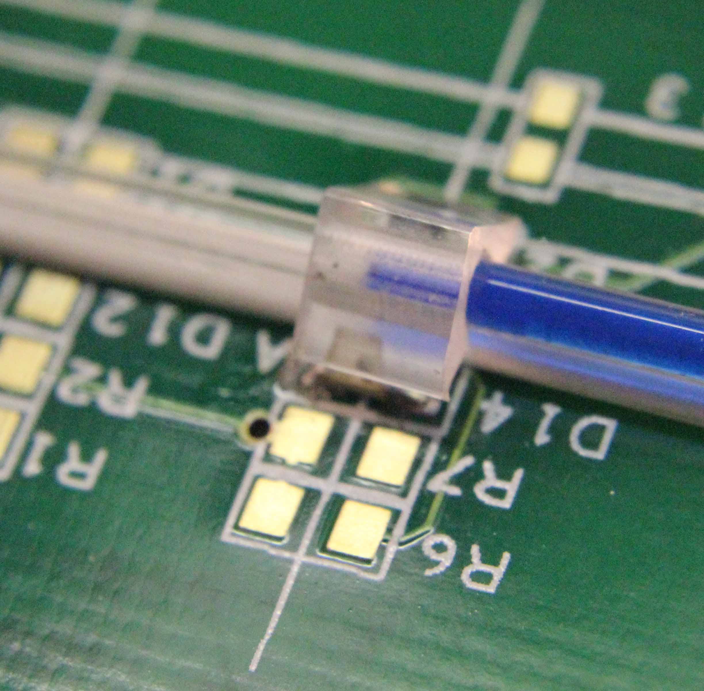
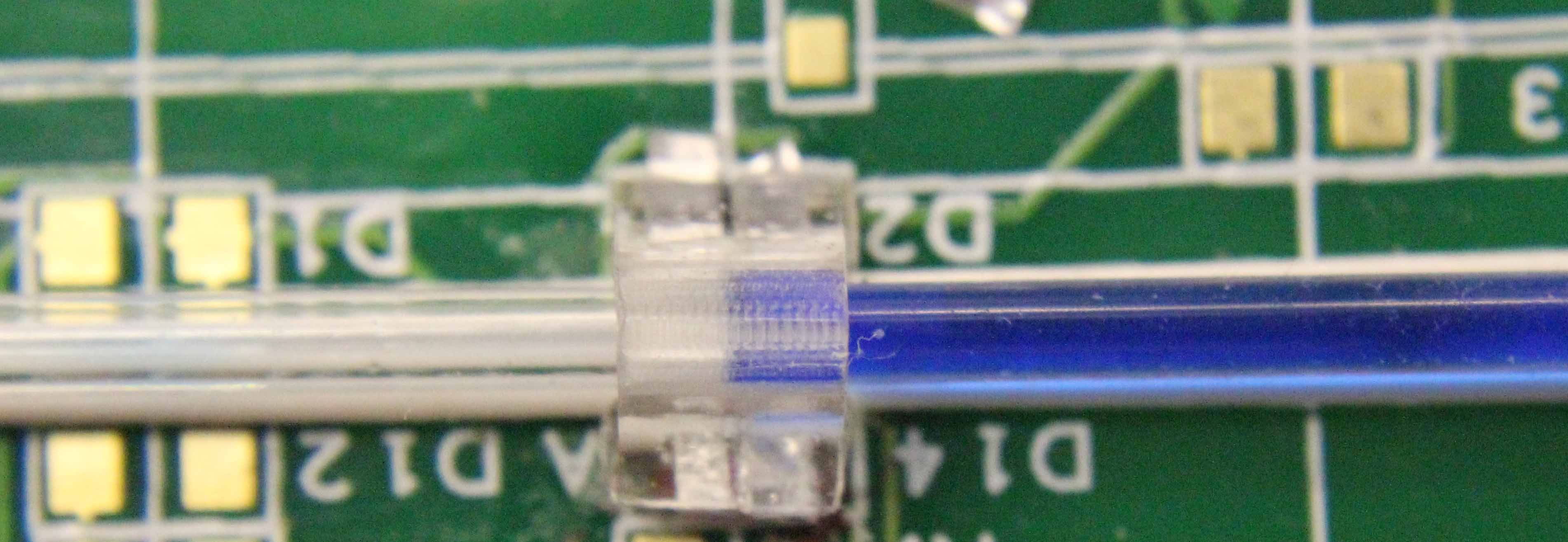
Figures 2 and 3 show the arrangement as constructed from the side and from above. The design enables the user to observe the meniscus at all points in its passage through the detector and using a travelling microscope precise distances can be determined for any particular physical arrangement.
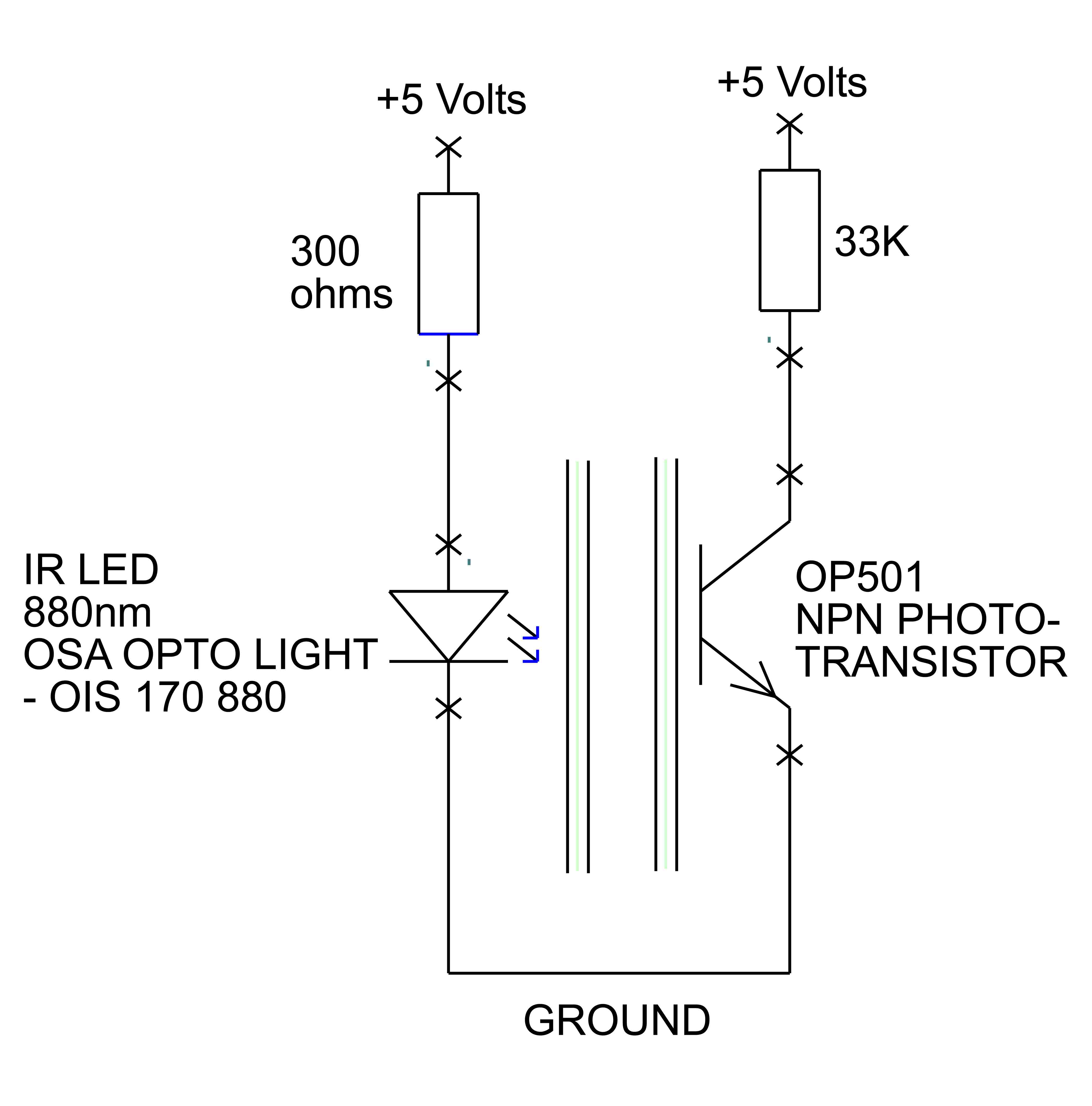
The simple circuit to energise the LED and detect the signal from the phototransistor is shown in figure 4. It was found that the LED produced too much infrared radiation if a series resistor lower than 300 ohms was used and that some adjustment of the collector resistor was necessary to obtain about 1 volt at the photo-transistor collector. This was the region in which the transistor was most sensitive.
Three optical modes were tested: visible light, modulated visible light and infra-red light. The difficulties of using visible light are obvious: daylight and artificial light both tend to reduce the signal-to noise ratio and can saturate the phototransistor at high intensities. Also AC noise from mains lighting was a further complicating factor. To some extent these difficulties were reduced by modulating the light from the LED at 5 kHz and passing the signal from the phototransistor through a high pass filter with a corner frequency of 1 kHz. This approach did not address the problem of phototransistor saturation and was considered to be over-complicated.
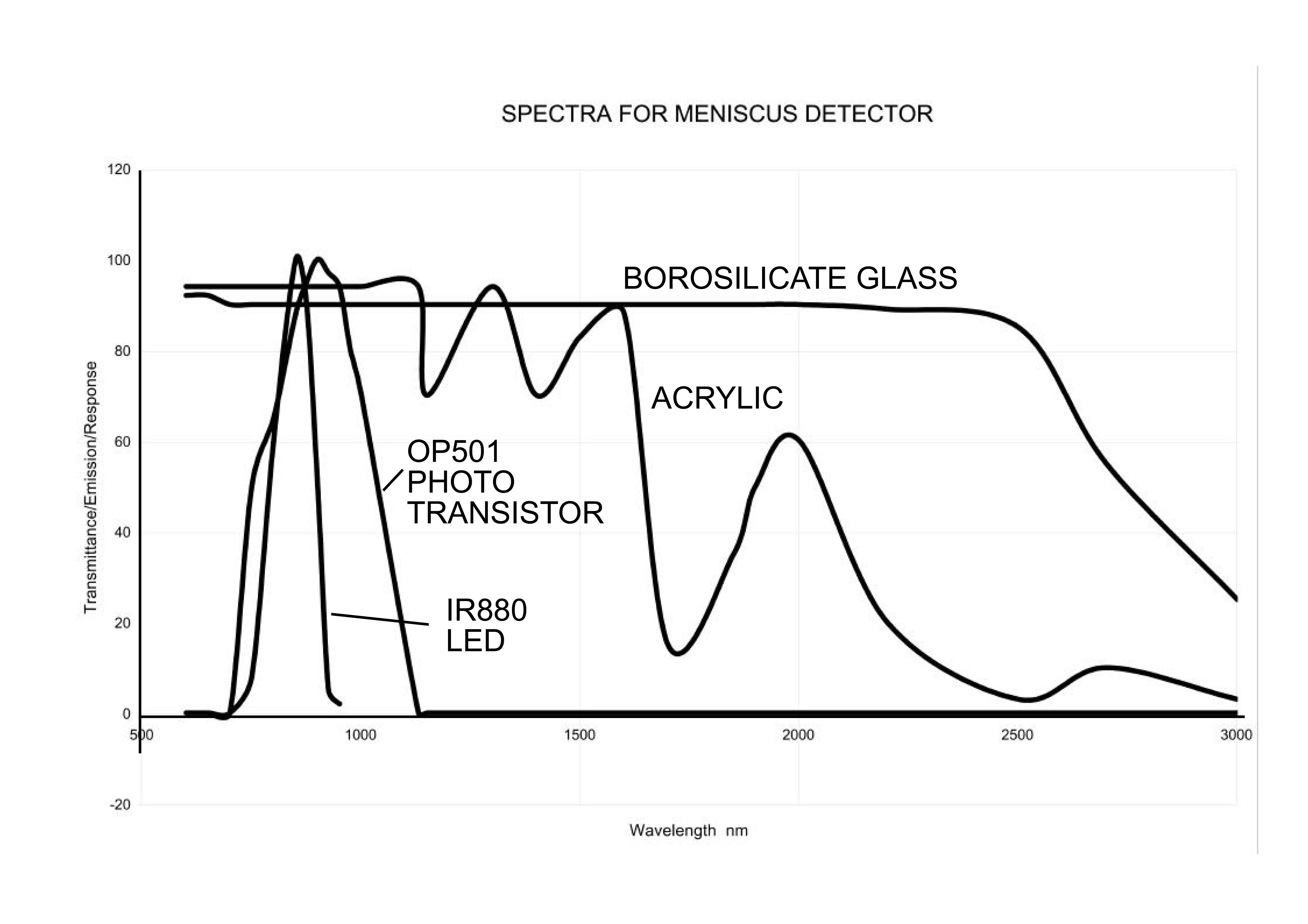
Figure 5 shows the absorption spectra of borosilicate glass and acrylic plastic together with the emission spectrum from the infra-red LED and the response curve of the phototransistor against wavelength. The choice of 880nm near-infra-red radiation is obvious from the comparison of the curves. Acrylic plastic and borosilicate glass are transparent to this wavelength, the OP501 phototransistor employed has a filter to remove visible light while the spectral width of the LED output is fairly narrow. It was found that incandescent light at high intensity has some effect upon the detector's performance but the arrangement had sufficient visible light rejection to enable its use at all reasonable light levels.
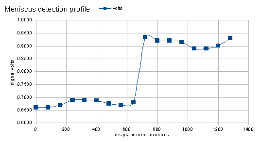
A micrometer syringe was used to advance fluid with a blue dye along the borosilicate tube. The voltage at the phototransistor collector was monitored and recorded for every 80 microns that the meniscus advanced. The results are shown in figure 6. A sharp transition in the voltage occurs when the meniscus crosses the 100 micron slit in the detector. By selecting the mid-voltage of this transition as a detection threshold, and allowing a 10:1 signal to noise ratio, the meniscus can be detected within 8 microns of the threshold position. This meets the desired specification of the detector.