
ALL MATERIAL COPYRIGHT KEVIN SCOTT 2011. LINKS TO THIS SITE ARE WELCOME BUT DO NOT COPY MATERIAL FROM THIS SITE TO ANY OTHER WEBPAGE.


If you find this site useful, please support it by making a donation of $1 to help maintain and develop it. Click on the PAYPAL DONATE button to do this safely. But there is no obligation - please avail yourself of the information and facilities of the site at no charge.
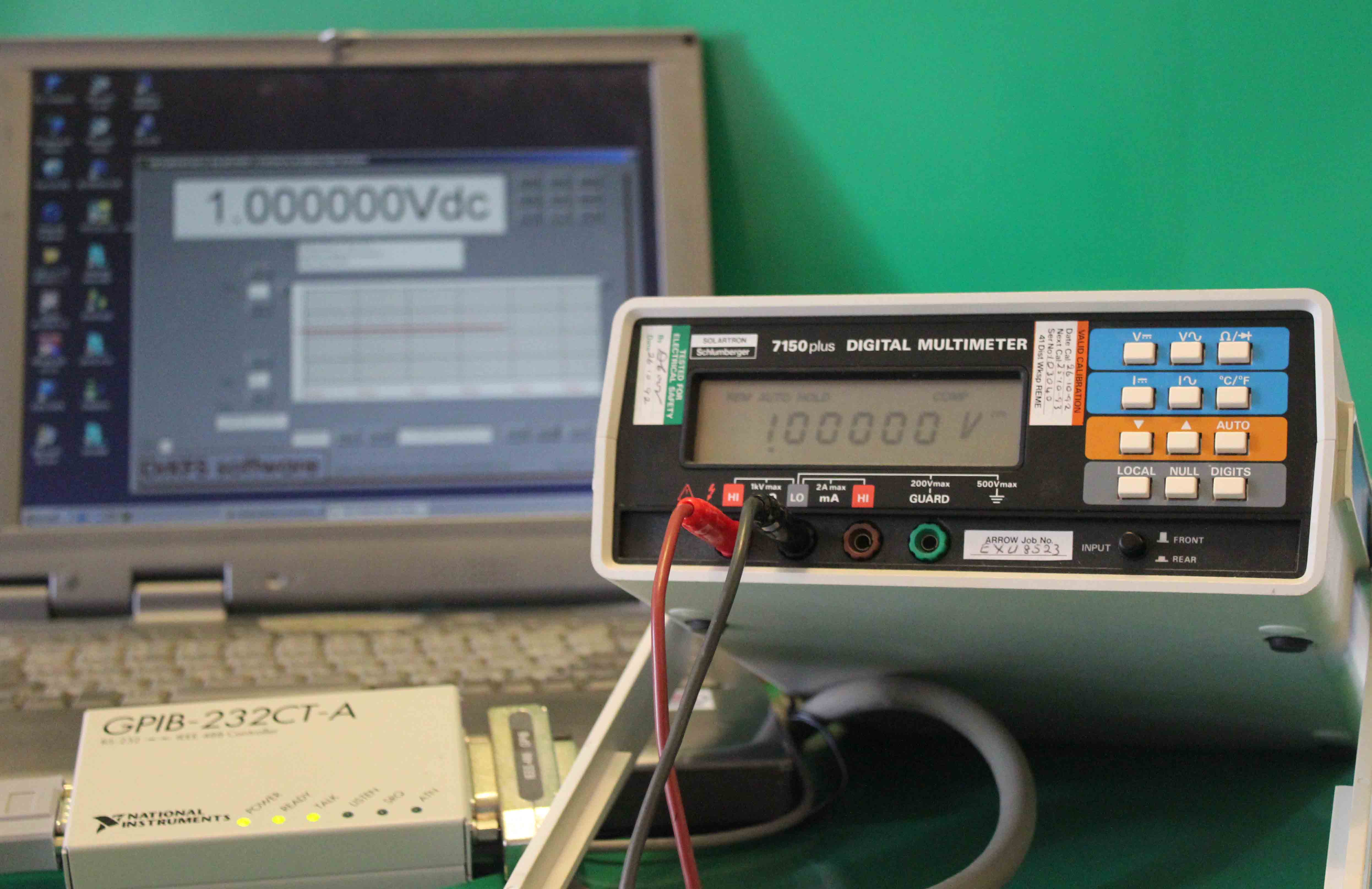
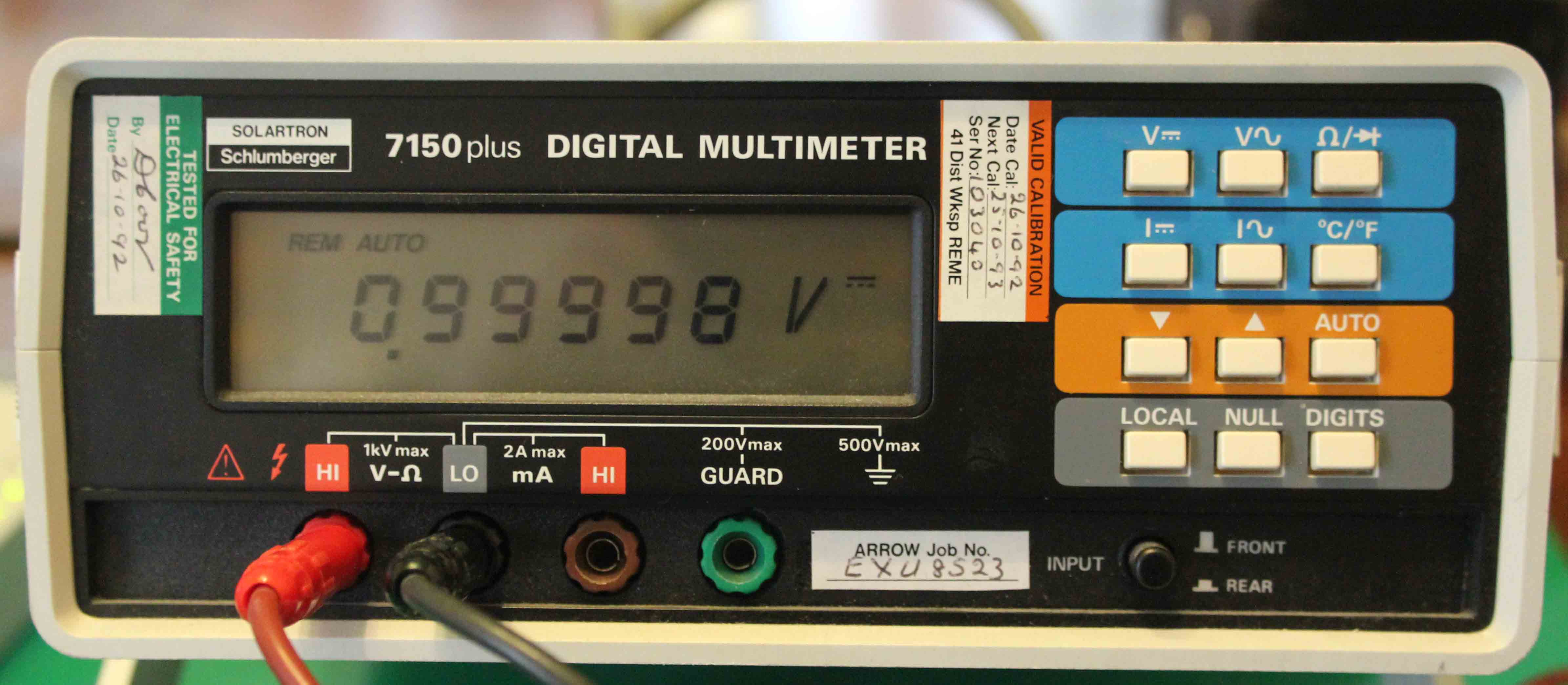
The Solartron 7150plus Multimeter is now out of production but appears to be widely available at relatively low cost and provides excellent performance as a 5-1/2 or 6-1/2 digit instrument. It has an accuracy of 0.002% +5 counts on the dc ranges. The user manual downloadable here, gives the full specification of the instrument.
Of particular interest to us here, is the facility of a GPIB or IEEE bus interface supplied at the rear of the instrument. There are, of course, many ways of exploiting this - via a IEEE card in a computer - or, as in this case, by the use of a National Instruments GPIB-232CT-A device which is an active interface between the IEEE port and a RS232 serial port.
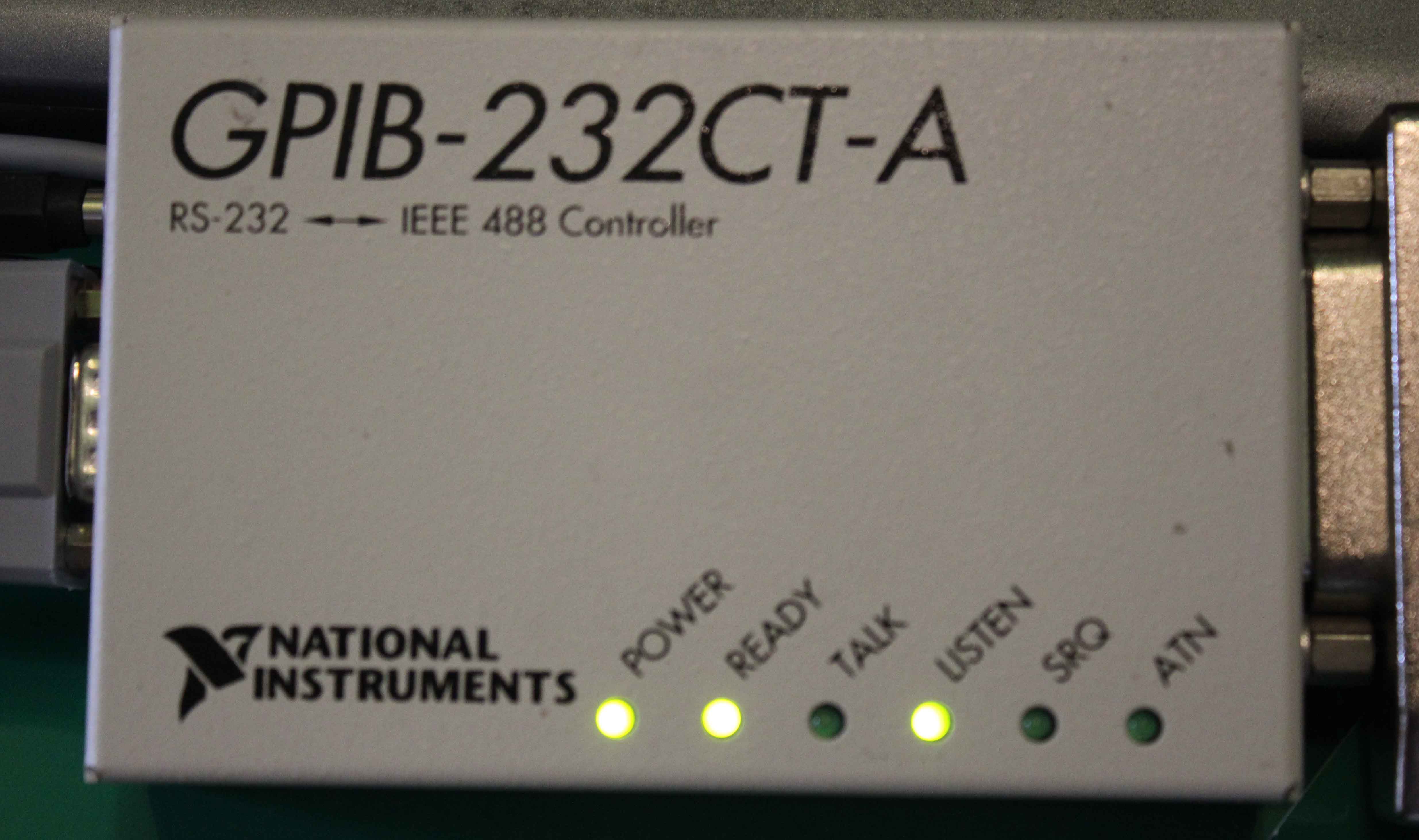
The GBIP-232CT-A is an interface which is relatively simple to exploit.The user manual can be downloaded here. The interface is either powered by 12 volts or from the mains depending on the version and is provided with a IEEE socket on one side and a 9 pin RS232 male connector on the other. A null modem cable is used to connect this with a computer's serial port, or, failing this, to a USB port via a USB/serial converter. Using the two manuals, the necessary scripts can be sent from the computer running a terminal program to enable control of the multimeter and the retrieval of its data. No doubt proprietary software is available for carrying this out. However, software has been written by the author to allow the continuous monitoring of the multimeter using a computer and the storage of the data via a CSV file accessible from Microsoft Excel.
Suitable software for the Windows environment will be downloadable from here. It is offered without guarantee and at the user's risk, but it contains nothing of which the author is aware, which could cause any damage. Nor does it contain any mal- or spyware, or viruses of any kind. The downloadable file is an executable setup file which, if run, will install the software. The operating system can be any Windows version from 2000 to Windows 7. The author is not aware of any bugs or conflicts it its use on any of these platforms.
The GPIB interface should be set up as described in the manual with a baud rate of 19200, parity off, 1 stop bit and 8 data bits.
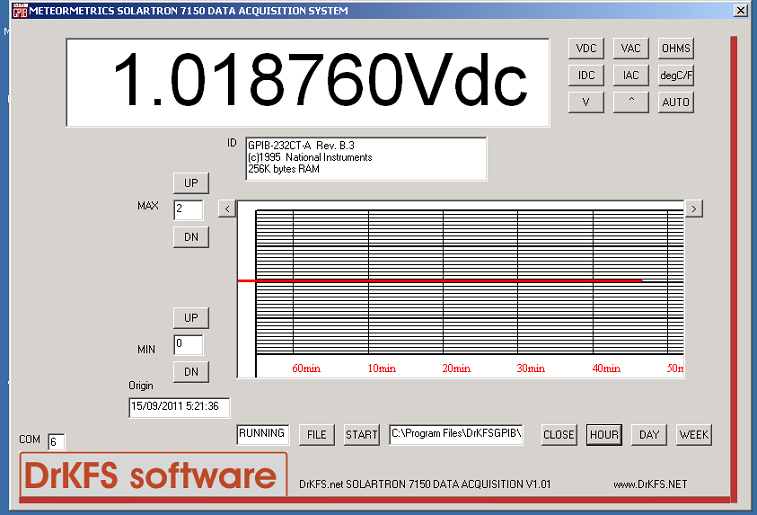
When the software is installed, a GPIB icon will appear on the desktop. Double clicking this will launch the application. The software first searches for a COM port which has a powered and ready GPIB-232CT-A attached to it. It searches all available COM ports from 0 to 25. If it fails to find a GPIB-232CT-A, it reports this and the application will then close. If it finds an active interface, it reports the comport number in the PORT box and the identity of the interface in the ID box.
The user should then click on the FILE button which will open a dialogue to select a file for data storage. This should be specified with a .csv extender. Clicking on the START button will initiate the data collection process. Clicking on HOUR, DAY or WEEK will set and calibrate the horizontal axis of the graph area and place the date and time of the origin of the plot in the ORIGIN text box. The left and right scroll buttons either side of the graph area allow the user to scroll horizontally through the data. After use, either the HOUR, DAY or WEEK but should be clicked to return the application to current data mode. The vertical scale setting buttons allow the range and position of the Y axis to be set as desired.
The buttons in the top right hand corner of the screen perform the functions of their counterparts on the instrument front panel.
The software should be regarded as a Beta test and the author would be grateful to hear of any bugs or difficulties for correction in future versions.