
ALL MATERIAL COPYRIGHT KEVIN SCOTT 2011. LINKS TO THIS SITE ARE WELCOME BUT DO NOT COPY MATERIAL FROM THIS SITE TO ANY OTHER WEBPAGE.


If you find this site useful, please support it by making a donation of $1 to help maintain and develop it. Click on the PAYPAL DONATE button to do this safely. But there is no obligation - please avail yourself of the information and facilities of the site at no charge.
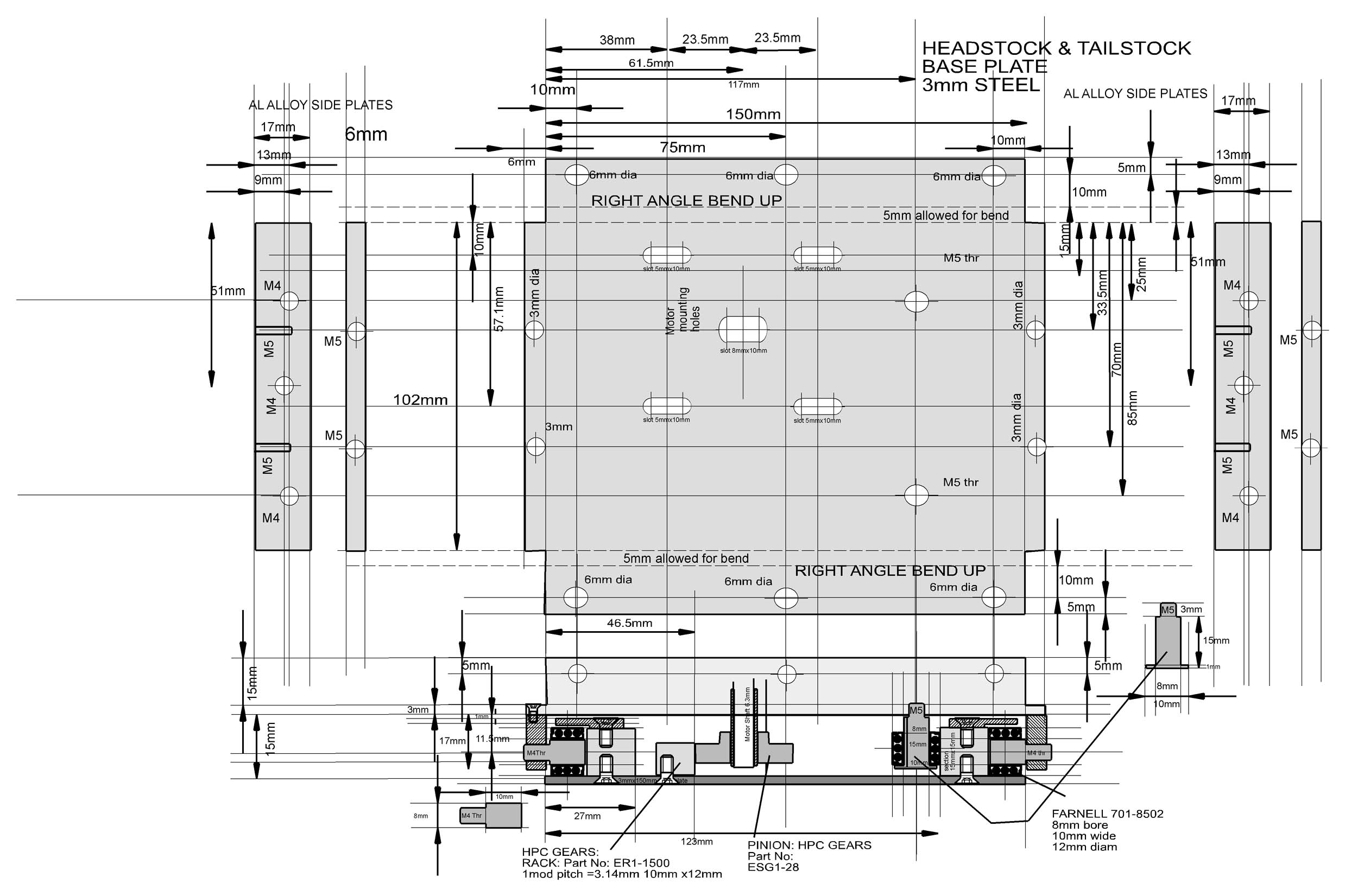
The diagram above shows the design of the base plate for headstock and tailstock. It consists of a 3mm steel plate cut drilled and bent as shown with a mounting for a stepper motor ( Farnell 713-4423 or similar). These mounts are slotted so the engagement of the pinion with the rack can be accurately set. The flanges bent at right angles carry the roller bearings and shake adjustment screws to regulate the engagement of the headstock or tailstock with the bed rails. The superstructure of both headstock and tailstock is shown below:
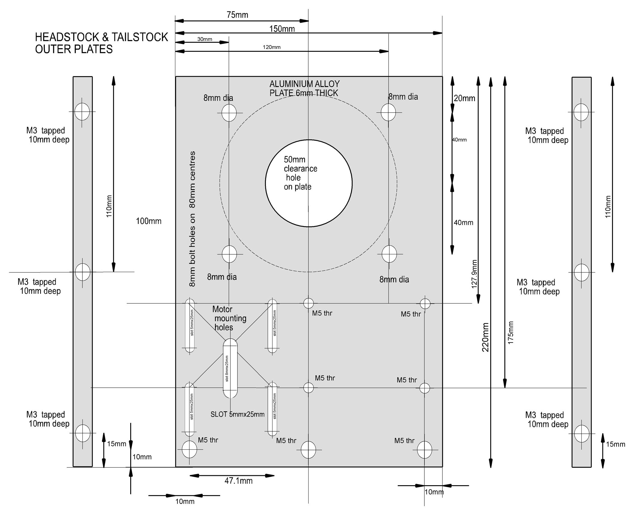
Between the vertical plates of the headstock and tailstock, a large automotive rear axle bearing is mounted. This is held in place by four bolts which clamp the bearing securely in place. The bearings provide about a 50mm bore for the lathe and, from the point of view of the lead they are required to bear, are greatly over specified. They could be replaced by a suitable casting with porous bronze inserts. Depending on the bearing used, the position of the mounting bolts may have to be adjusted.