
ALL MATERIAL COPYRIGHT KEVIN SCOTT 2011. LINKS TO THIS SITE ARE WELCOME BUT DO NOT COPY MATERIAL FROM THIS SITE TO ANY OTHER WEBPAGE.


If you find this site useful, please support it by making a donation of $1 to help maintain and develop it. Click on the PAYPAL DONATE button to do this safely. But there is no obligation - please avail yourself of the information and facilities of the site at no charge.
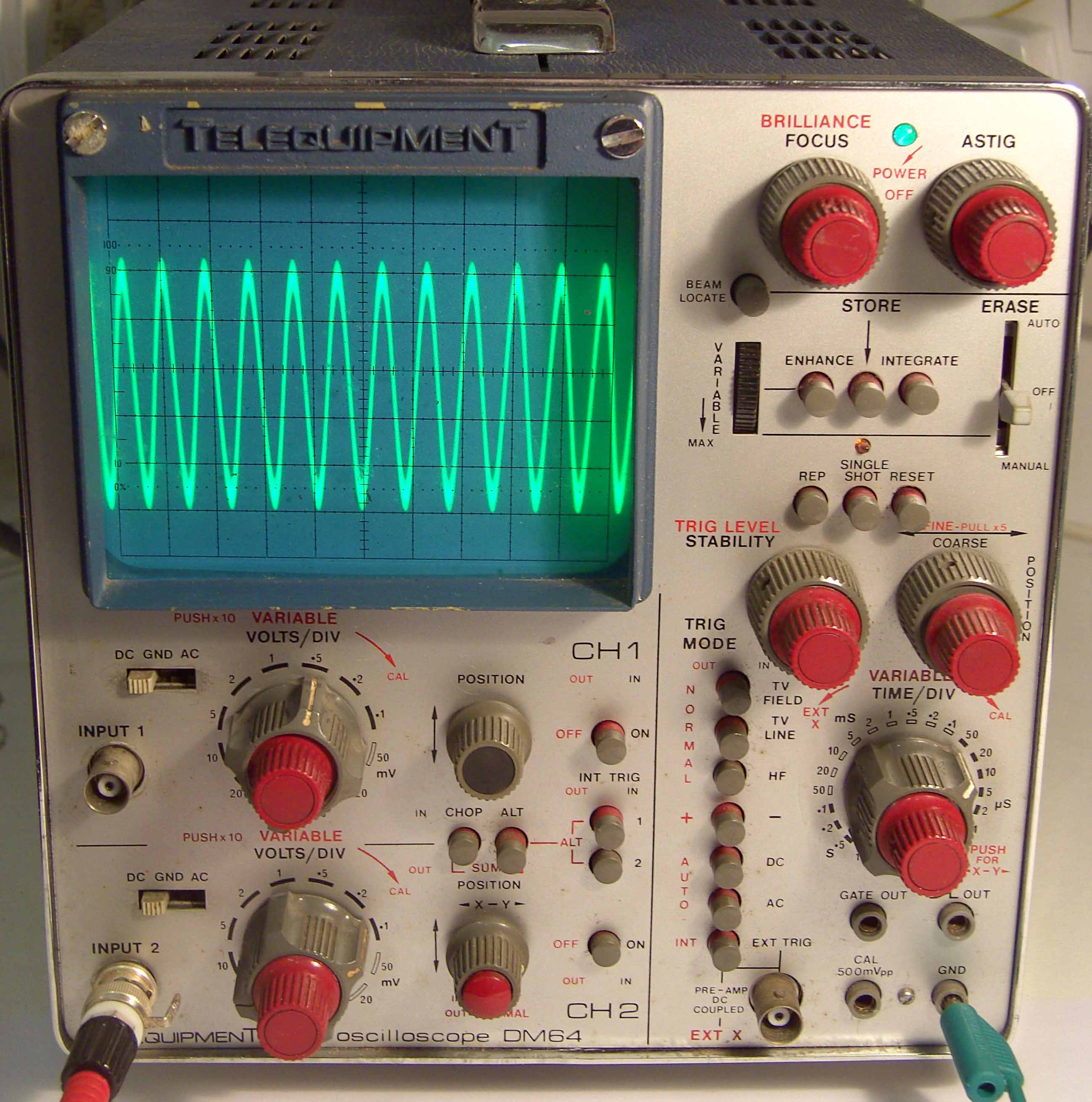
The Telequipment DM64 Analogue Storage Oscilloscope is now obsolete and out of date, and, in common with instruments of its generation (1970s) was somewhat more demanding on the user, than equivalent modern instruments. The triggering was more difficult to set up and the display did not exhibit the stability of modern counterparts.
Nonetheless, the DM64 was a great oscilloscope not least for its analogue storage facility which brought all the assets of trace memory without the disadvantages of digital methods. The user of an analogue oscilloscope is always “closer to the signal” than his digital colleague who has layers of sampling, digital processing, and software separating him from the signal under investigation.
The author thus considers the DM64, as old and as out of date as it is, to be worth repairing. This article describes the procedures used to correct faults as they arose in the author’s particular instrument. Thus it will be in no wise comprehensive, but may be useful to others who wish to restore their DM64 oscilloscope.
A PDF of the MANUAL for the Telequipment DM64 can be downloaded here
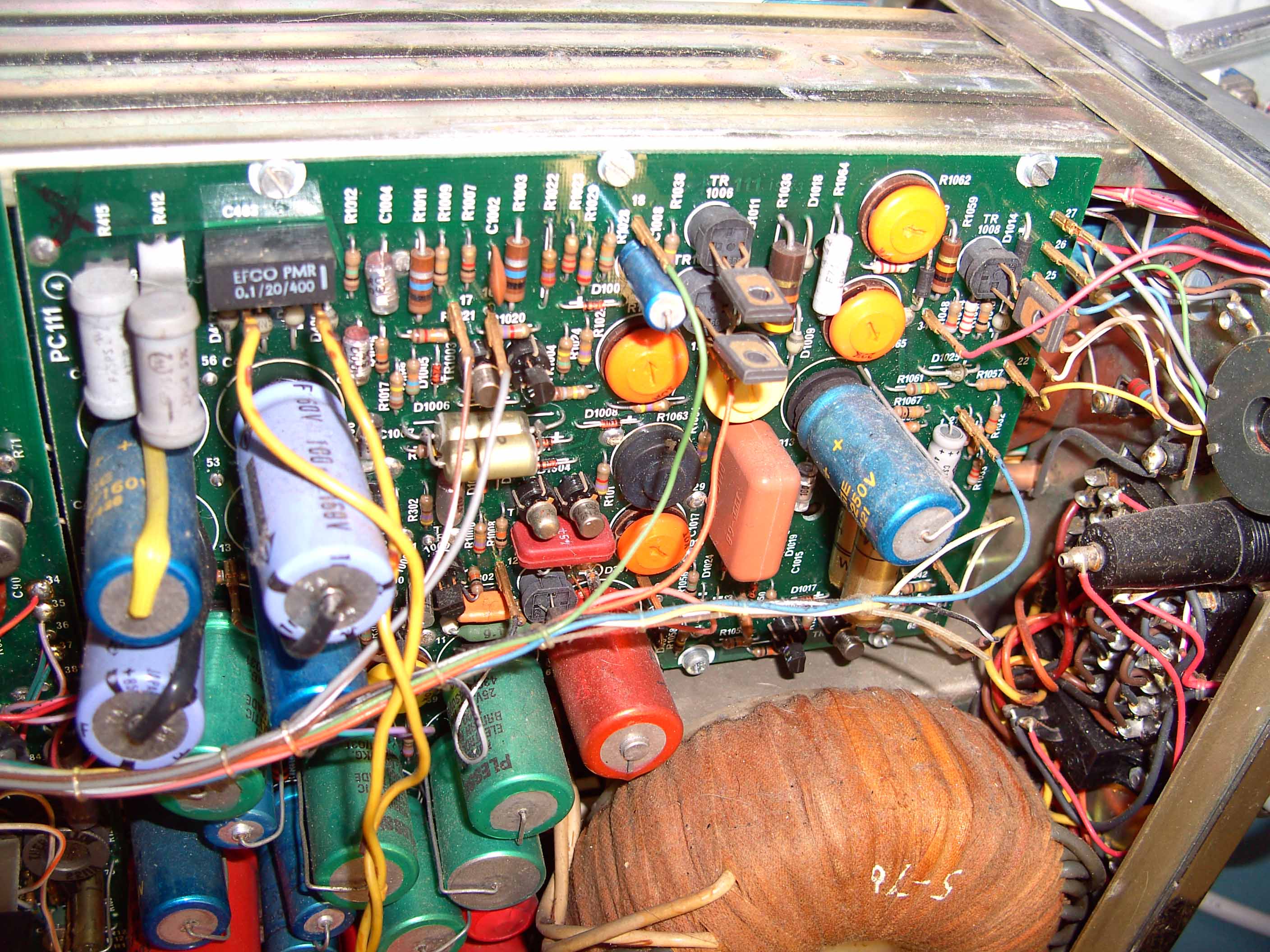
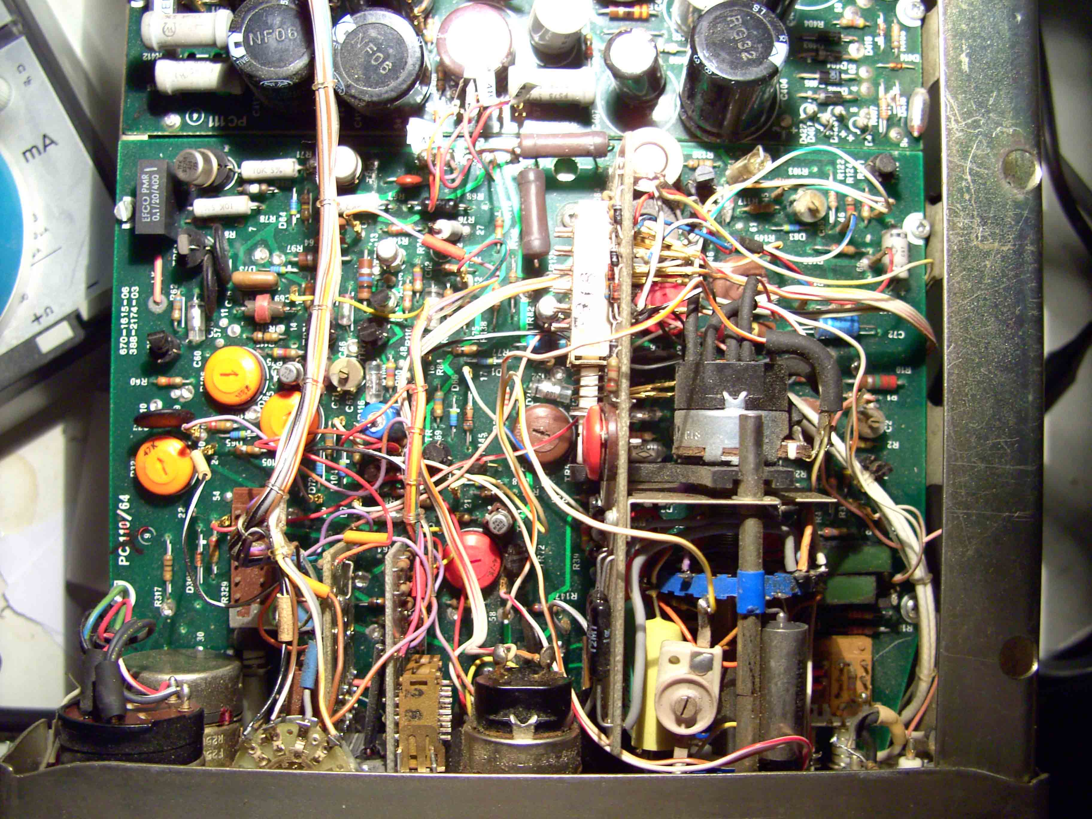
This includes schematics, parts lists, circuit description and set up procedures and is a comprehensive asset without which the repair project would be scarcely possible. The original manual contained colour PCB drawings which can be downloaded as zip file containing 2 JPG images hereIn the early stages of the repair (detailed below) the power supply failed and a resistor on the power supply board began to over heat. This was thought to be R414 a 33 ohm resistor which would carry a heavy current if C414 (1000microfarads 25v) short-circuited. (see schematic in manual)
As the board had to be removed to replace this component, it was decided to replace all the capacitors on the board. There are some 54 connections to the power supply board, 24 on the component side and 30 on the solder side. The points at which they connect to the board are numbered on one side or the other. Prior to their removal, all the leads from wiring harness were carefully labelled. The connections on the component side are all via push on connectors, but those on the solder side are soldered.
| LOCATION | WIRE |
| 65 | black/white |
| 20 | yellow |
| 21 | blue |
| 14 | pink |
| 15 | orange |
| 18 | green |
| 16 | grey |
| 17 | brown/white |
| 13 | brown |
| 52 | green/purple |
| 45 | red/orange |
| 46 | purple/orange |
| 47 | green/red |
| X1&X2 | yellow twisted pair connected to pins adjacent to C403 |
| 34 | red |
| ON THE CRT ASSEMBLY | |
| 26 | green |
| 27 | grey |
| 25 | blue |
| 24 | light brown |
| 22 | yellow |
| 23 | white |
| 52 | red |
| 50 | grey |
| ON THE SOLDER SIDE OF THE POWER SUPPLY BOARD | |
| 2 | purple |
| 29 | purple/white |
| 61 | yellow |
| 1 | purple/blue |
| 63 | orange |
| 41 | red/white |
| 37 | blue |
| 6 | white/blue |
| 40 | purple/yellow |
| 43 | red/orange |
| 68 | red |
| 58 | yellow |
| 35 | white |
| 62 | orange |
| 57 | red/black |
| 58 | green/blue |
| 55 | purple/orange |
| 54 | red |
| 32 | white |
| 52 | white |
| 36 | yellow |
| 31 | green/white |
| 67 | purple |
| 56 | black |
| 56 | orange |
| 44 | purple |
| 63 | black |
| 30 | light brown |
| 39 | black/blue |
| 38 | black/white |
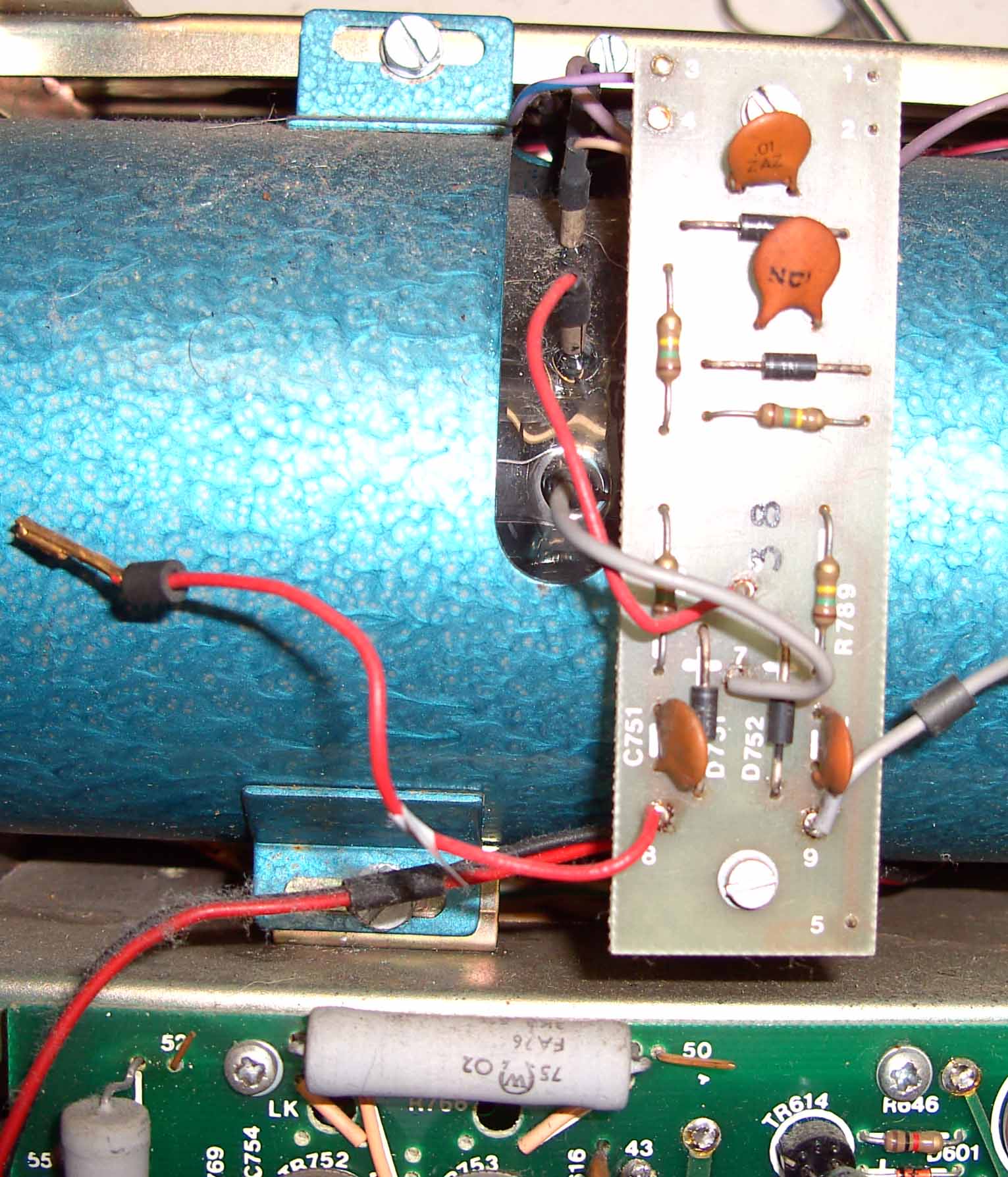
The tube assembly must be removed to label and disconnect the wiring harness on the solder side of the board. This is done by disconnecting the wiring to the tube sub-assembly ( after labelling) and the removal of three screws which secure the tube. The two screw securing the mains connector are removed and the mains connector detached. The chrome screws holding the plastic rear plate are removed and the plate set to one side. The CRT base is removed. The Tube can now be taken out of the instrument and set to one side.
This exposes the wiring on the solder side of the power supply board, which can be carefully labelled and disconnected. The screws securing the board are withdrawn and the board removed.
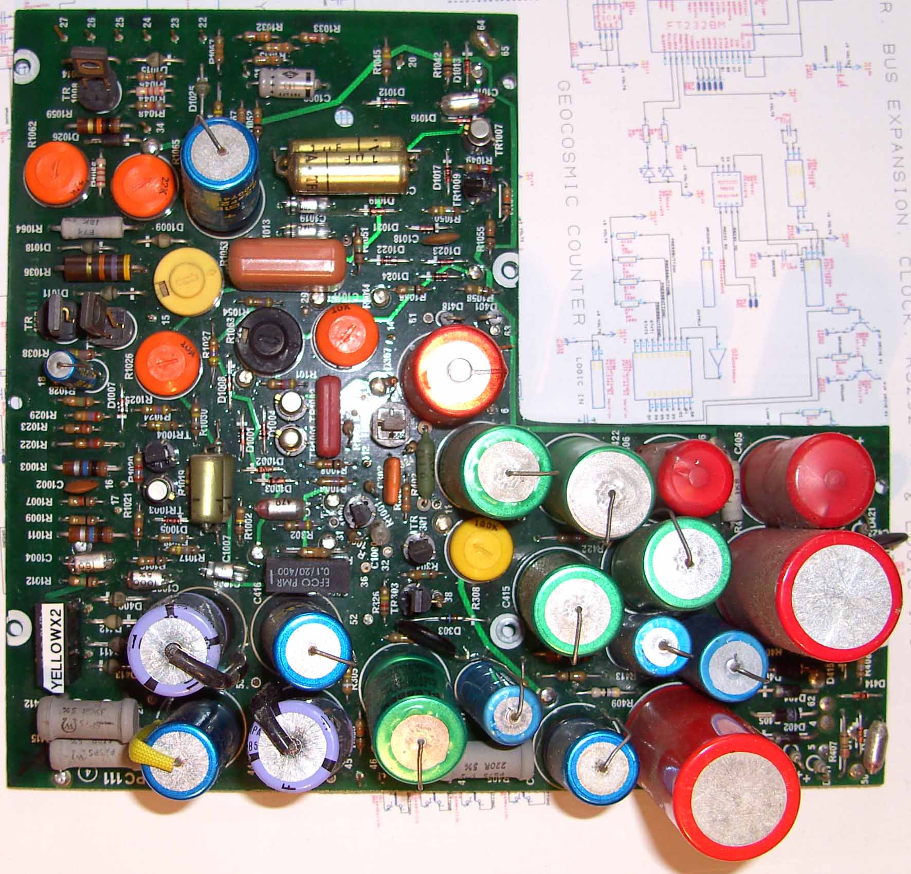
The capacitors are carefully unsoldered and replaced with new components.
The PCB is then replaced and the connections to it above and below reconnected. The tube is
reinstalled and its connections restored.
After replacing the capacitors in the power supply board, the general “feel” of the instrument was much
improved: The brightness control functioned more smoothly, the trace was sharper and clearer and
more stable. It was felt that further work on the instrument was justified because the final
outcome would be a useful and reliable instrument.
What follows in this section is a log of the repair of the timebase circuitry:
(a) Application of an AC signal to channel 1 (or 2) produced a vertical line on the screen the height
of which appeared to be correct in relation to the applied signal and the attenuator setting.
(b) A corresponding trigger signal appeared at the trigger input at R42 or R41.
(c) All the transistors in the trigger circuit were removed, tested and replaced. All appeared OK
(d) Voltage measurements indicated that the transistors were OK in the timebase circuit.
(e) switching to XY mode gave a horizontal trace confirming that all was well with the X amplifier.
(f) Examination of the timebase circuit revealed that the ramp voltage was at its maximum or above at
13.6V at the emitter of TR72. Evidently the flyback was not functioning.
(g) The continual high voltage at the timebase output deflected the beam fully to the right of the
screen as expected and caused R125 to carry sufficient current to reach about 150 deg C as
measured by an IR non-contact thermometer. On switching to EXT X, this temperature dropped back to about
50 deg C.
(h) Difficulty was encountered in determining the status of the two bistables
( TR66 & TR68) and (TR73 & TR74)
(i) When cathode of D1 is connected momentarily to -14V rail, nothing happens to the trace,
but when it is disconnected, the trace flies back and then return rapidly to its right-hand position.
(j)The -14V rail is at -10V but when disconnected at 110/35, the power supply side rises to -14 Volts
the current taken by the -14v line was 66 mA. It was found that R414 nominally 33 ohms (5%, 500mW) had
doubled in resistance and was replaced. this raised the -14V rail to -12.2 which compared favourably
with the working oscilloscope at -12.5V
(k) A comparison of voltages between the oscilloscope under repair and a another DM64 with working timebase
showed that the emitter of TR67 was at 104.5 volts on the faulty unit and at 16.9V on the
correctly functioning oscilloscope. TR67 was found to have blown and was replaced.
This resulted in the display being blanked, but a -14V signal applied to the cathode of
D1 resulted in a visible trace as described in (i) above. The flyback blanking is now working.
(l) The timebase circuit (miller integrator) is still not flying back when the ramp voltage
has reached its maximum value.
(m) Checked D71 by substitution OK.
(n) Checked the integrity of connections to Time/Div Switch. All ok.
(o) Found TR72 to be faulty : replaced. Monitoring the emitter of TR72 it was observed:
(i) On switching on the instrument the miller integrator ramps correctly from about 2 v to 12 volts
( the span of this ramp being correctly adjustable by R106. The range switch has the correct effect
on the ramping speed.
(ii) When the sweep maximum is reached, the integrator does not reset automatically, but it does so
when a multimeter probe is connected to the base of TR73.
(iii) After such a reset, the miller integrator can be triggered by a negative pulse applied to
the anode of D1.
(p) Adjustment of trace length via R106, enabled the miller integrator to reset correctly when the
ramp hit the maximum value.
(q) TR68 was found to be faulty and was replaced, whereupon the beam was correctly unblanked for
the duration of the trace.
The failure of the miller integrator to reset at the end of the ramping process was attributed to a faulty
TR68 and TR72, and incorrect setting of R106 and the one-shot adjusting preset R112. When the transistors were
replaced and these presets adjusted correctly the timebase was found to operate normally.
The analogue storage section was not working on the instrument under repair. The storage section of the electronics on PC111 consisted of three triggered monostables the outputs of which are connected to the erase amplifier and thence to the CRT STB electrode. A check of all the transistors showed that TR1005 had failed. On replacement, the storage function worked perfectly! An easy repair!
The beam focus control appeared to have no effect on the screen trace. The control on the front panel varies the current through a small light bulb which shines on a phototransistor, thus forming an optoisolator situated in the EHT supply screened container. The bulb was checked and was working, but the phototransistor evidently had failed. A suitable replacement has not, to date, been identified. The servicing of the focus system was also hampered by the difficulty in accessing the focus potentiometer connections and in replacing that component. Since the beam was reasonably well focused in any case, this problem was not pursued further. Probably the best approach would be the replacement of the phototransistor and the provision of a separate focus control at the rear of the instrument. This has not yet been carried out.