ALL MATERIAL COPYRIGHT KEVIN SCOTT 2011. LINKS TO THIS SITE ARE WELCOME BUT DO NOT COPY MATERIAL FROM THIS SITE TO ANY OTHER WEBPAGE.


If you find this site useful, please support it by making a donation of $1 to help maintain and develop it. Click on the PAYPAL DONATE button to do this safely. But there is no obligation - please avail yourself of the information and facilities of the site at no charge.
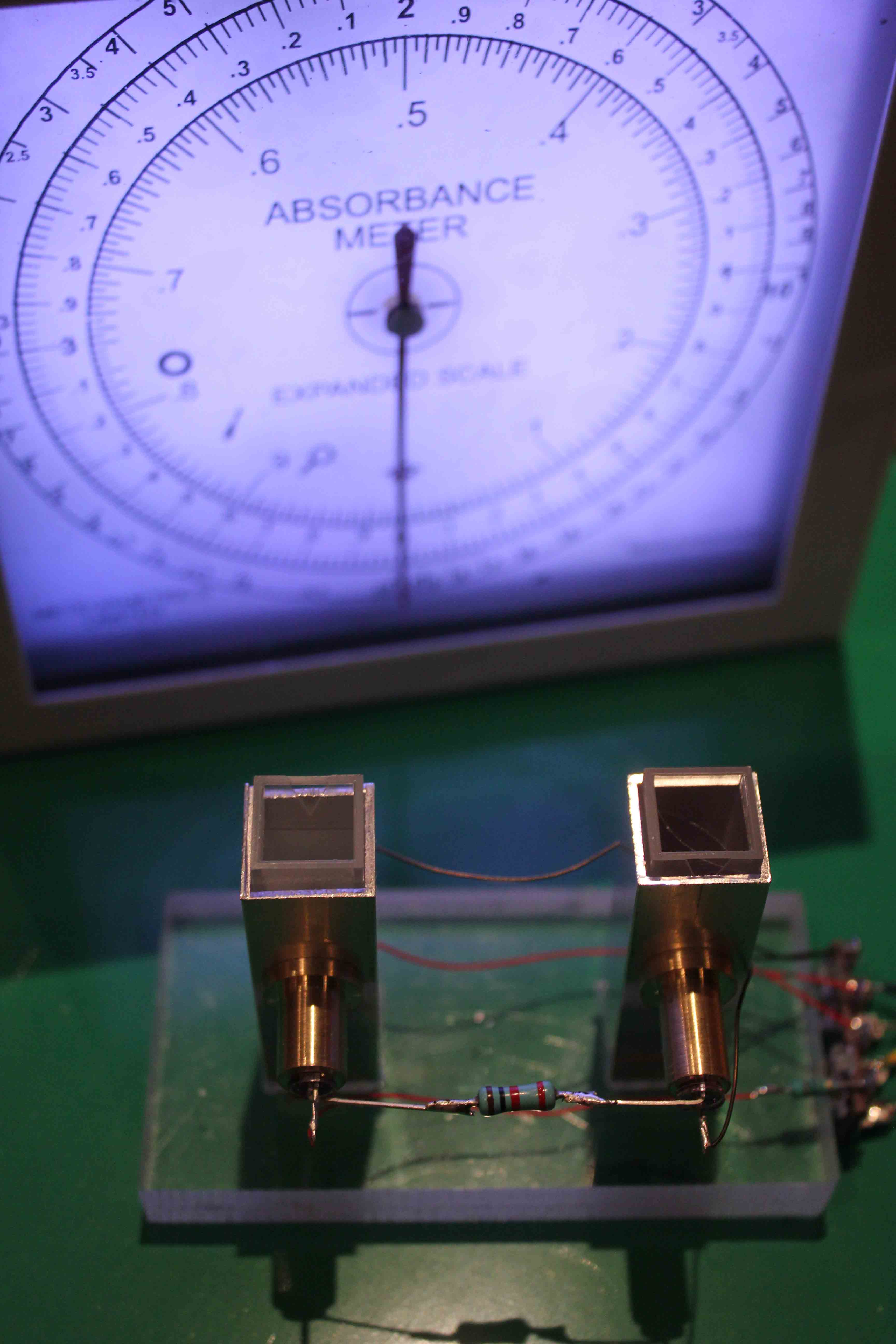
Described here is a simple two-channel photometer of moderate accuracy, designed to investigate the absorption of 880nm near infra-red radiation by substances which may be useful as dyes for this wavelength. The immediate purpose is to identify suitable materials to enable fluids to be detectable optically using 880nm light. Since no great accuracy is required for this application, the simplest possible design has been used to give an approximately linear absorbance scale presented in a highly readable form from the simplest possible optical arrangement. The reference and sample channels were fitted with 880nm light emitting diodes and filtered phototransistors to match the wavelength. The photo current in each of the photo-transistors was fed via a current mirror to a log ratio amplifier. The output of this was displayed by a modified Meteormetrics Digital Dial Instrument.
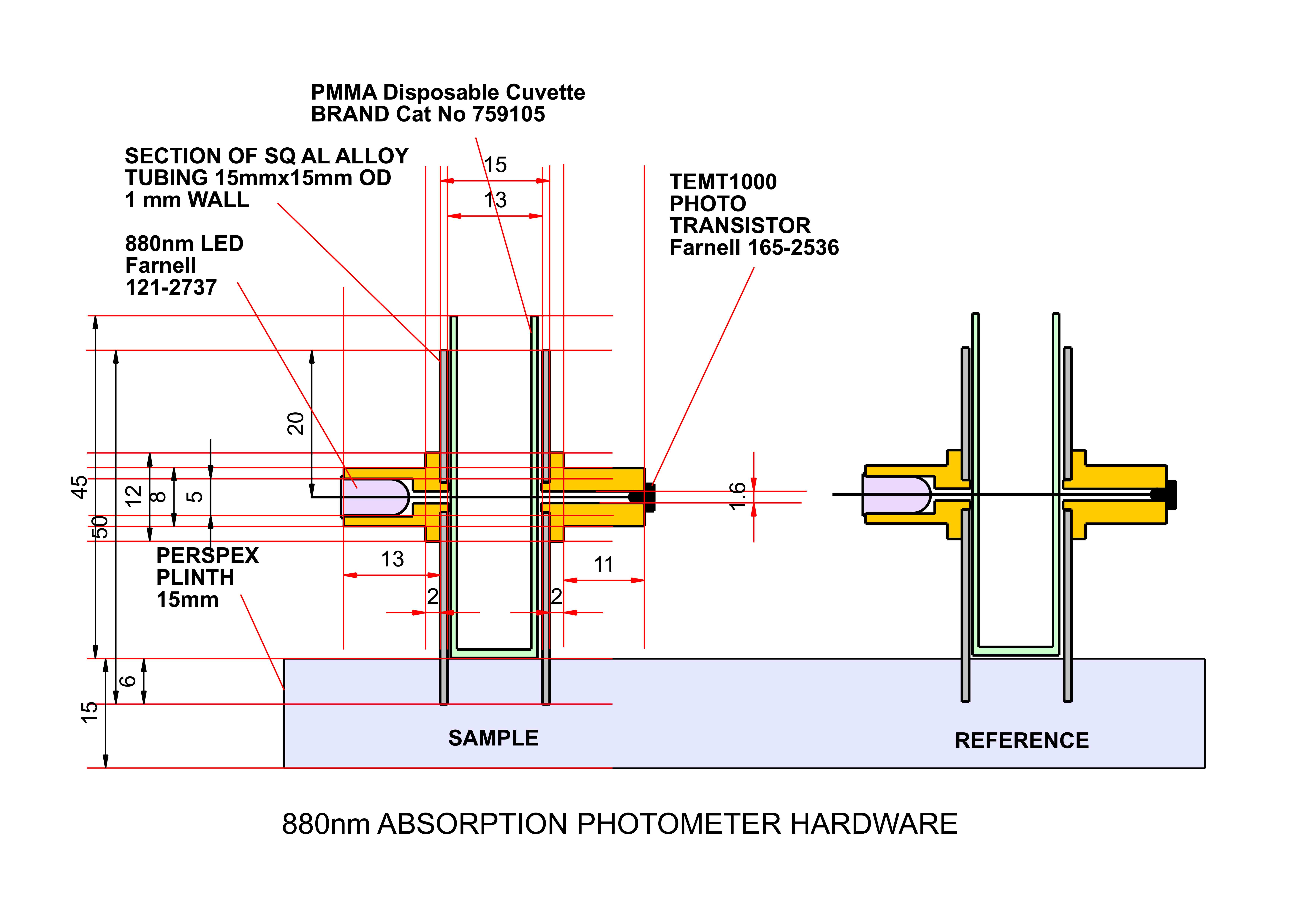
The Absorption Cell is shown diagrammatically below. A perspex plinth carried two sections of square aluminium tube just sufficient in internal dimension to allow standard 10mm cuvettes a sliding fit inside. Brass turned mountings carried the diodes and phototransistors which were held in place using cyanoacrylate adhesive. The current through the diodes which were wired in series, was adjusted by means of a series resistor in order that the light intensity generated by the diodes might lie in the linear region of response of the photo-transistor.
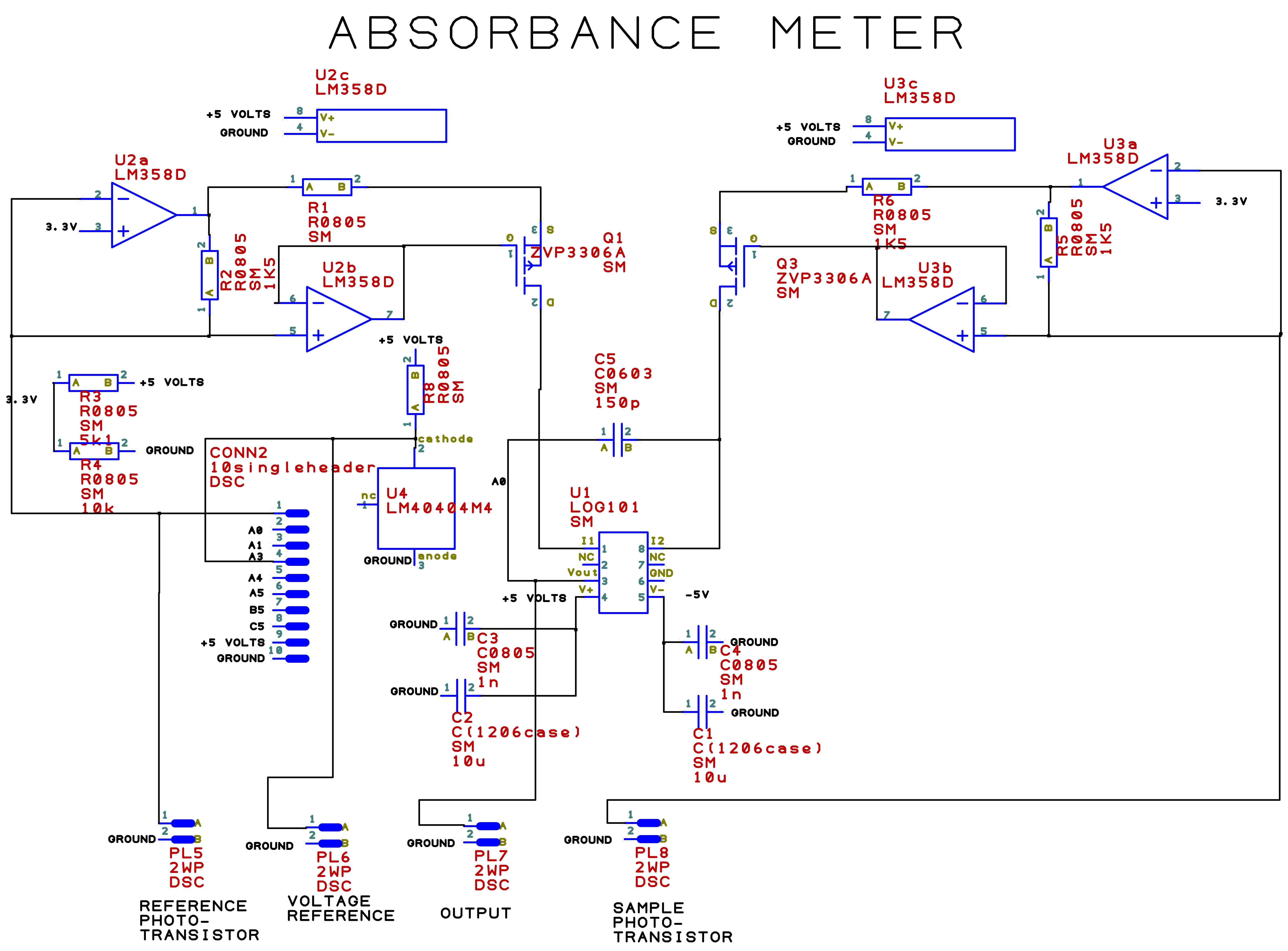
The electronics are shown in the schematic below. The circuit consists of two current mirrors one each for the sample and reference channels of the photometer. Dual operational amplifier U2 and mosfet Q1 form the reference current mirror and U3 and Q3, that for the sample side. The current flowing through each respective phototransistor generates a reflected current which flows into the logarithmic ratio amplifier U1 which generates a voltage of 1 volt per decade of the ratio of the input currents. For the purposes of A/D conversion a reference voltage of 4.096 volts is generated by U4. This together with the output voltage from U1 is fed to the analogue inputs of the Meteormetrics Meteor2020 Digital Dial display unit. This is fitted with a convenient scale plate calibrated linearly in Absorbance Units and logarithmically in Transmittance Units.
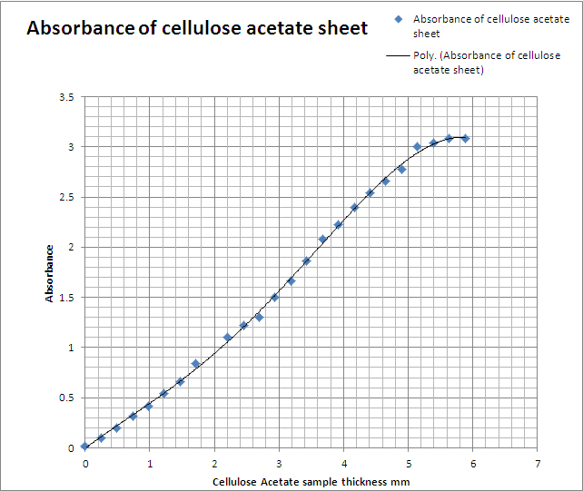
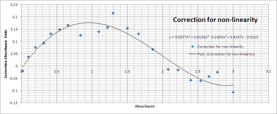
An estimate of the performance of the photometer was made by measuring the absorbance of an increasing number of sheets of cellulose acetate which was found to absorb at 880nm to an appreciable degree. A 0.245mm thickness of the acetate film showed an absorbance of approximately 0.13. 10mm wide strips were cut to fit a standard cuvette and for each number of strips a total absorbance reading was taken. The results are shown plotted on the right.
The appreciable non-linearity was traceable to the optical response of the phototransistors and this non-linearity was minimised by adjusting the 880nm light level to enable the use of the most linear part of the transistor characteristic. It was found that a current of 2.6mA through the light-emitting diodes represented an optimum in this respect.
To correct for the non-linearity, the average absorbance per acetate thickness was obtained across the whole experimental range and this used to generate a correction to be applied to the Absorbance reading to eliminate the effect of this non-linearity. A plot of this correction against absorbance is shown below: