
ALL MATERIAL COPYRIGHT KEVIN SCOTT 2011. LINKS TO THIS SITE ARE WELCOME BUT DO NOT COPY MATERIAL FROM THIS SITE TO ANY OTHER WEBPAGE.


If you find this site useful, please support it by making a donation of $1 to help maintain and develop it. Click on the PAYPAL DONATE button to do this safely. But there is no obligation - please avail yourself of the information and facilities of the site at no charge.
The Argon Discharge Ionisation Detector is a development on previous discharge ionisation detectors.(1) The construction is shown in Figure 2.
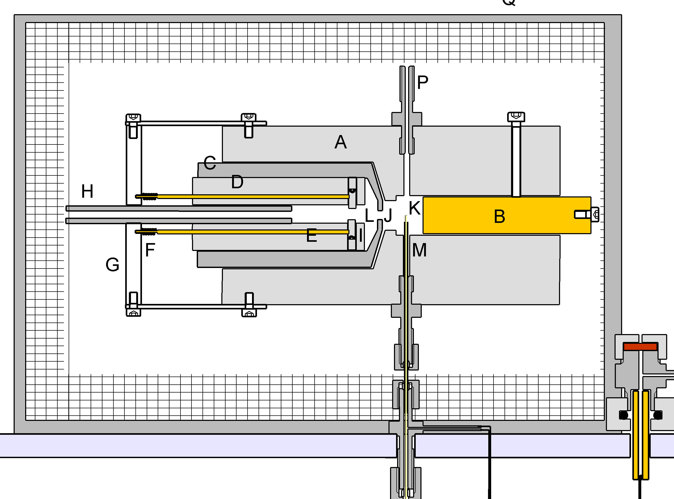
The detector is machined from a PTFE rod 25mm in diameter. It is bored as shown to accommodate brass electrode B and the assembly CDE. C is a turned Dural tube with a narrow bore J of 1 mm at one end. It is electrically grounded and consitutes a Faraday Screen between chambers L & K. D is a tube machined from PTFE having three longitudinal bores, the centre one of which carries a stream of argon via PTFE tube H which is a push fit into D. The two other bores carry brass rods which bear upon 1mm diameter platinum electrodes I which are separated by 1 mm. The brass rods are spring-loaded and retained in position by PTFE plate G. In use one of the rods is grounded and the other raised to a potential of 1.7kV via a 1 Megohm resistor. This causes a continuous arc between the electrodes I through which the Argon stream passes. The Arc chamber L is bored out to 5mm in diameter for about 2mm of its length. The Argon flow, leaving the arc chamber L via orifice J enters the ionisation chamber K wher it meets effluent from the column. Any compounds in this effluent steam which have an ionisation potential of less than 11.4 electron volts are ionised. A polarising voltage of 1kV is applied to the electrode B via a 10Gigohm resistor. The ion current is measured using an electrometer amplifier connected to M.
The response and linearity of the detector were measured for Butane using a logarithmic dilution vessel. (Photo right) This consists of a stirred vessel of known internal volume fitted with a gas inlet and outlet.
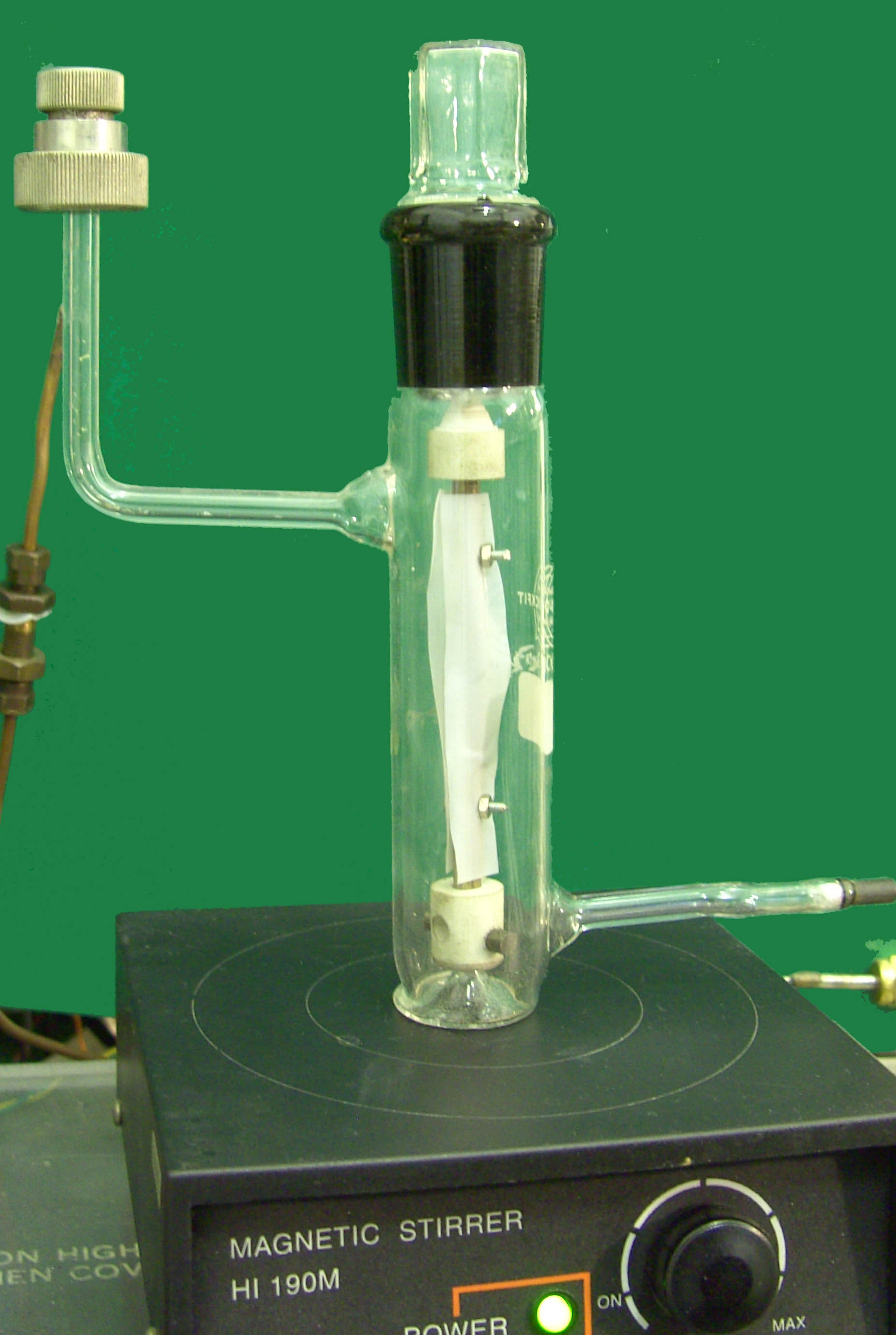
If the internal volume is V and the gas volume flowrate is Q, the concentration
of hydrocarbon in the vessel is C0
at time T0, then the concentration at time T is given by
C = C0exp(-Q(T - T0)/V)
As long as V and Q are known the concentration is known for all times after the starting concentration is
established. This is achieved by injecting a known quantity of hydrocarbon into the inlet stream to
the vessel. The outlet stream is fed to the detector, there being no necessity for any chromatographic
column. The profile obtained from the detector takes the form of an exponential decay which is precisely
of that mathematical form if the detector is strictly linear in its response. Deviations from linearity
are betrayed by the departure of the signal decay from the exponential form.
The response of the detector to Butane was measured for various Argon flowrates through the arc chamber and for
different arc currents. The results are shown in Figures 4 and 5. Figure 4 shows that there is an increase in the response
of the detector with increasing Argon Arc flowrate. When the Argon passes through the arc, there is some ionisation, but the most significant effect is the
generation of metastable argon atoms which are sufficiently activated to ionise organic molecules with which they collide. Evidently
the number of such metastables generated per second increases with the Argon flowrate.
Figure 5 shows the expected effect of increasing the arc current. The response of the detector to Butane increases but
the slope of the curve progressively diminishes. Clearly about 1.5mA is a reasonable current at which to operate to give optimum response without undue
electrode burn.
The prototype Argon Discharge Ionisation Detector showed a dynamic range of about 3 orders.
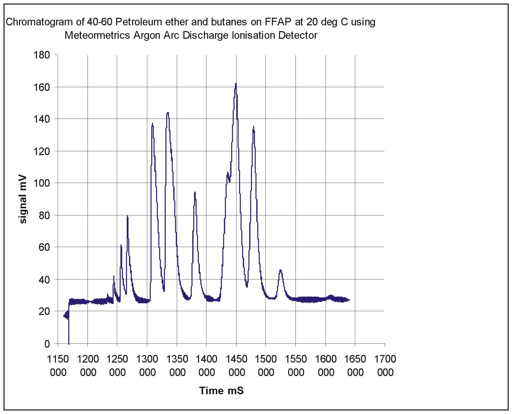
The parameters are much as might be expected of the detector except that the ionisation efficiency is a good deal lower than that of the standard Argon detector activated by a radioactive source. This may be a function of geometry or a lack of secondary processes which improve the efficiency in the standard detector. The ionisation efficiency is the parameter which needs next to be improved. A Chromatogram of butanes and the constituents of 40-60 Petroleum Ether demonstrates the usefulness of the detector.
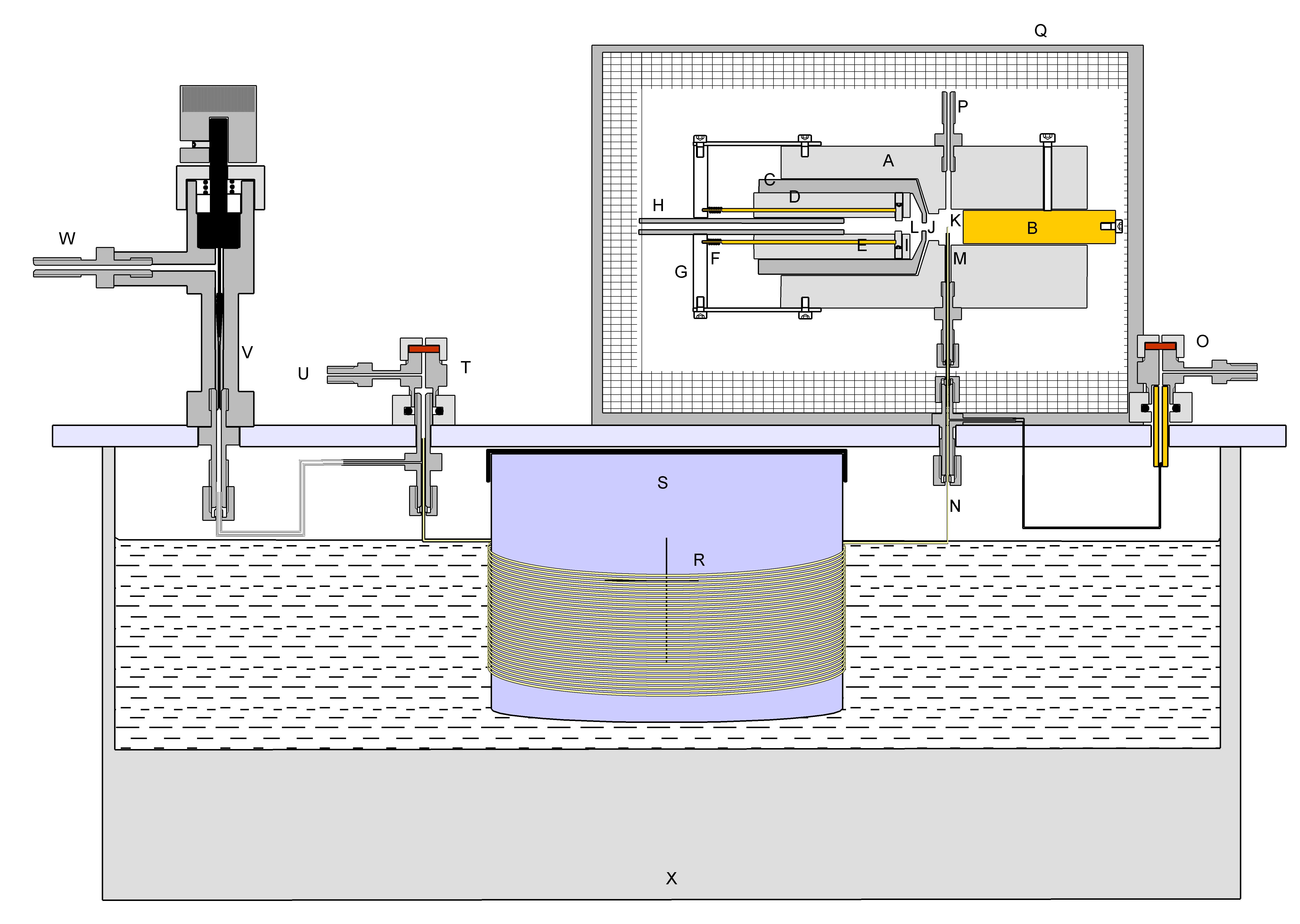
Figure 1: The experimental capillary gas chromatograph
used to characterise the Argon Discharge Ionisation Detector.
The construction of a gas chromatograph is essentially a simple matter. What is needed is a
chromatographic column, in this case a capillary column R (Alltech 19688 FFAP 15metres ID 0.54mm
Film thickness 1.2 microns), through which a carrier gas flows (In this case, Argon). The column was mounted on a drum S
about 15cm in diameter, this being possible because the column was of a coated quartz construction,
patented by Hewlett Packard which is remarkably flexible. The carrier gas was supplied via an injection port T
and a splitter arrrangement divided the carrier gas between the column and a vent valve V. This enabled
a small, controlled flow of gas through the column and a more rapid flow through the injector which
facilitated the injection of a small sample occupying initially only a very short length of the column.
The column passes into the ionisation chamber of the detector to minimise band-spreading which would otherwise occur in
interconnecting tubes.
The chromatograph depicted in figure 1 was operated at room temperature. The waterbath X was at 20 deg C. For more general
applications three heaters would have to be supplied, for the column itself, for the injection system and for the detector,
but for the purposes of testing the Argon Discharge Ionisation Detector using low molecular weight hydrocarbons, these
heaters were omitted.
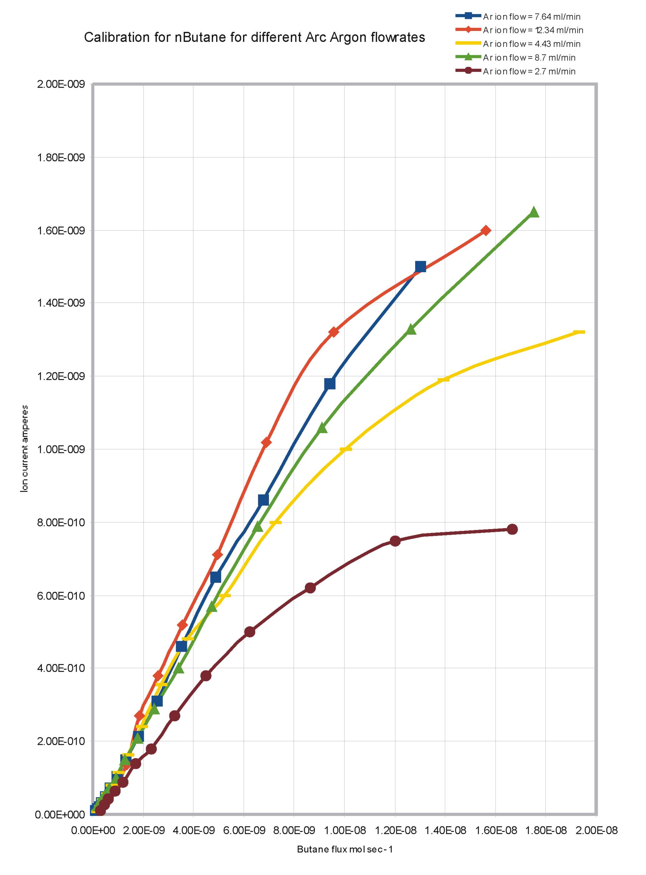
Figure 4, Response curves of the Argon Discharge Ionisation Detector to Butane for different Argon Arc flowrates.
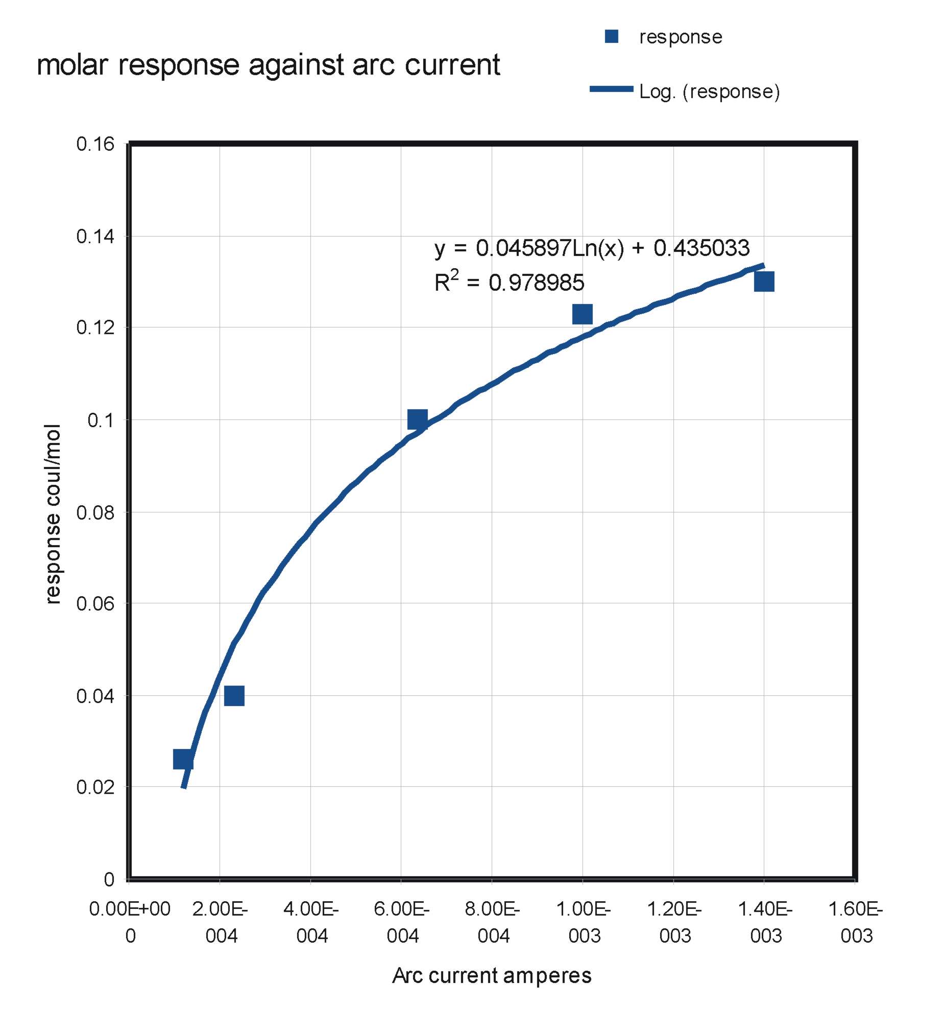
Figure 5, Response of the Argon Discharge Ionisation Detector to Butane against different Arc currents.