
ALL MATERIAL COPYRIGHT KEVIN SCOTT 2011. LINKS TO THIS SITE ARE WELCOME BUT DO NOT COPY MATERIAL FROM THIS SITE TO ANY OTHER WEBPAGE.


If you find this site useful, please support it by making a donation of $1 to help maintain and develop it. Click on the PAYPAL DONATE button to do this safely. But there is no obligation - please avail yourself of the information and facilities of the site at no charge.
There may be, in the laboratory, the occasional demand for a convenient source of refrigeration but this requirement is of such infrequency that the storage of liquid nitrogen or solid carbon dioxide is hardly justified. The Peltier cryostat described here is intended to meet the infrequent need of a convenient refrigerant, and although it can reach only -30 - -40 C, this can be sufficient in many circumstances where depressed temperatures are needed. It has been designed so that a small vacuum trap can be accommodated or it can be used on the laboratory bench for custom cooling of samples prior, say, to their being sealed into ampoules. It is used by the author in the manufacture of thermometers.
Some preliminary experimentation identified the critical design features of a Peltier cryostat. Peltier elements are widely available in the form of a "ceramic sandwich", typically 40mm square and about 4mm thick. They are available in a range of electrical specifications, typically carrying up to about 10 amps, having a resistance of 1-3 ohms. Some data on the version used in this design (TEC1-12706) is available here. Some general notes on the use of thermo-electric coolers is available here. The Peltier elements can be configured in parallel or in series or in a series-parallel combination. Parallel configurations confer thermal transfer capacity while series arrangements confer higher temperature differentials between source and sink. A series- parallel configuration was first tried and is depicted in the drawing below:
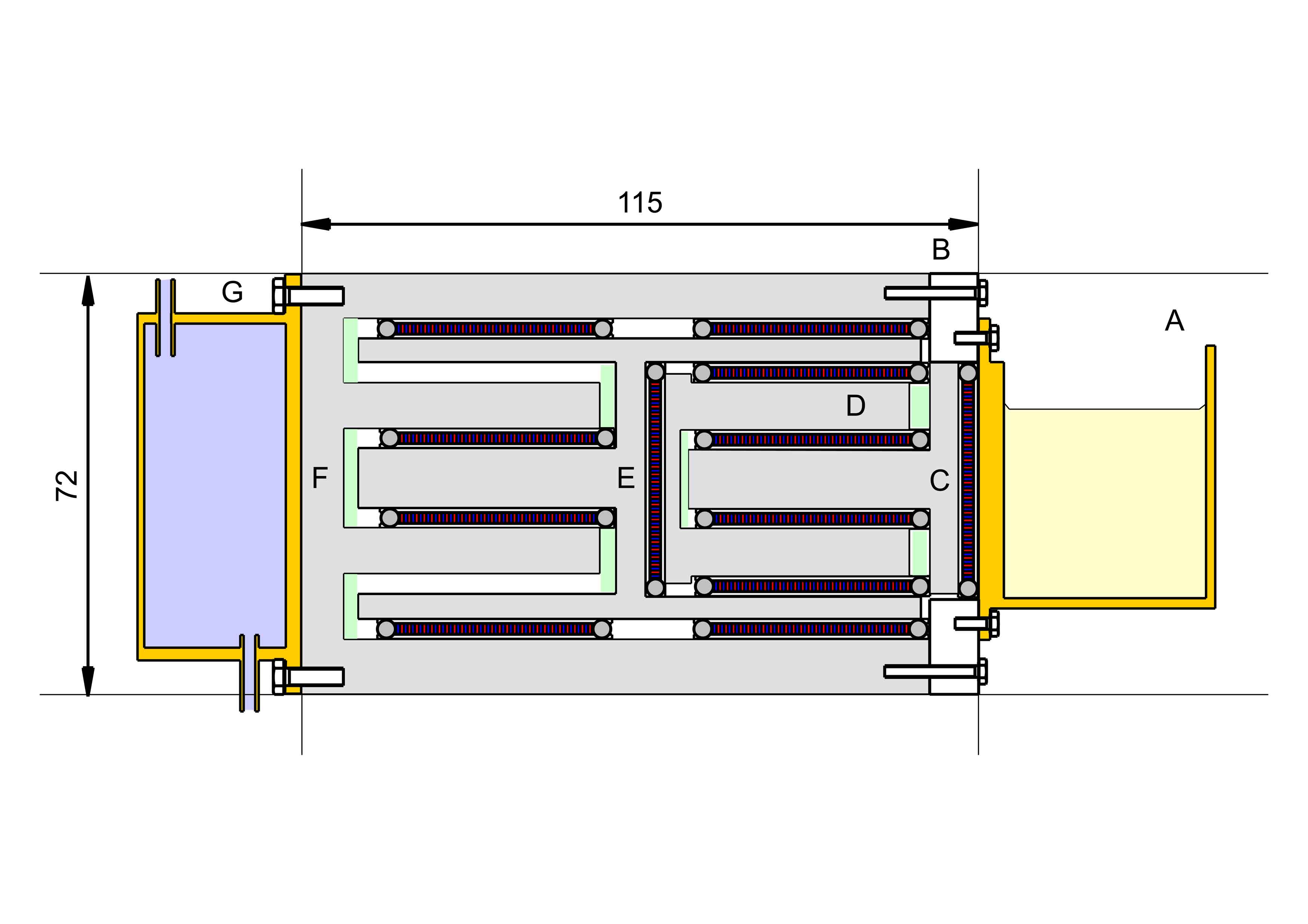
A series-parallel multiple element cryostat. A brass bath containing acetone A is closely thermally coupled to a peltier element and thence to aluminium alloy element C which, in turn has two peltier units connecting with Alloy element D. This in turn has three peltier units connecting it with alloy element E. Element E has 6 peltier units connecting it with alloy element F, which is thermally coupled with the water cooled brass envelope G. The performance of this combination was disappointing: a minimum temperature achievable of about -8 degrees C. The poor performance was probably due to the long thermal paths between the elements.
The design eventually adopted was a parallel design using 9 Peltier units depicted in the diagram below:
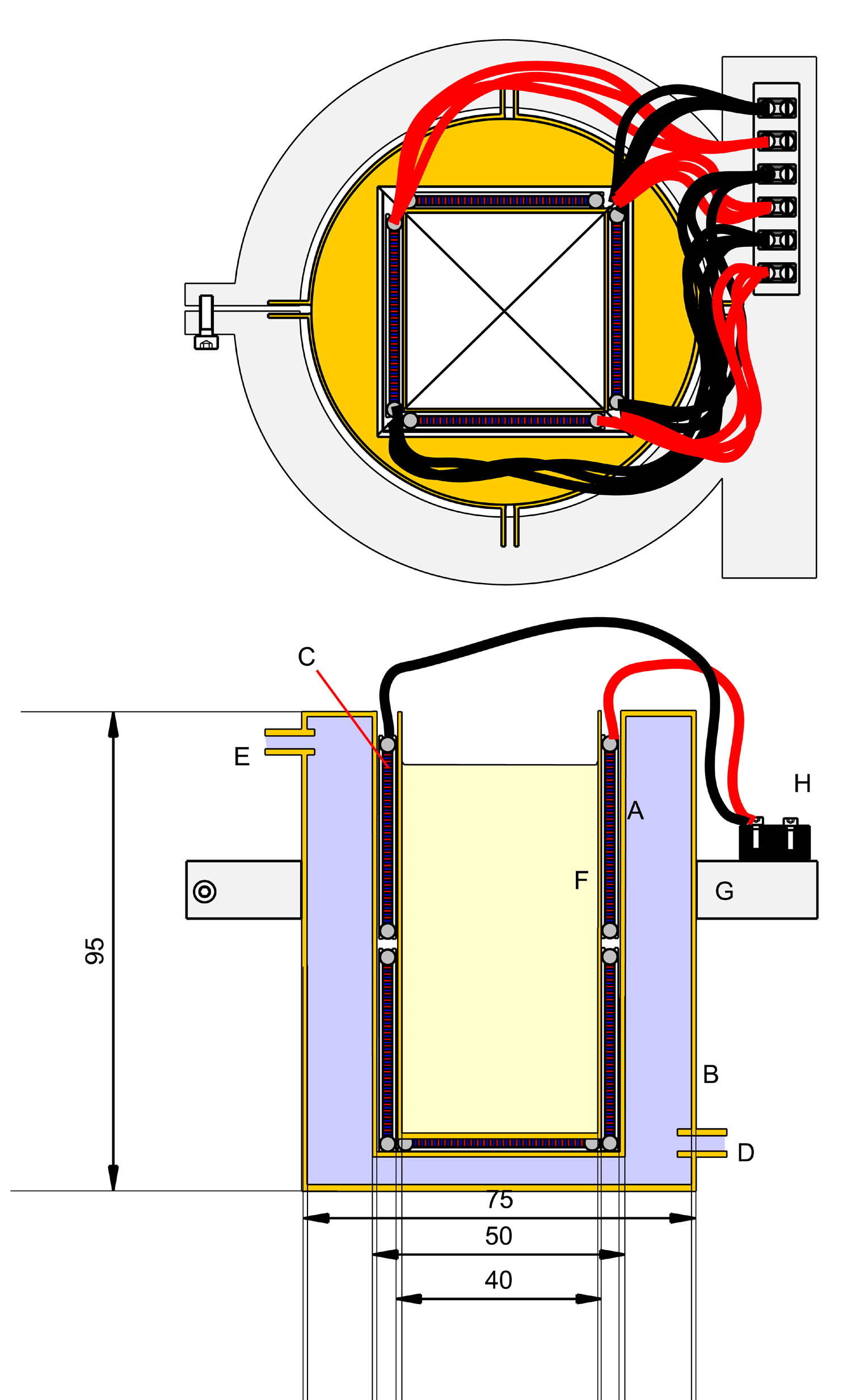
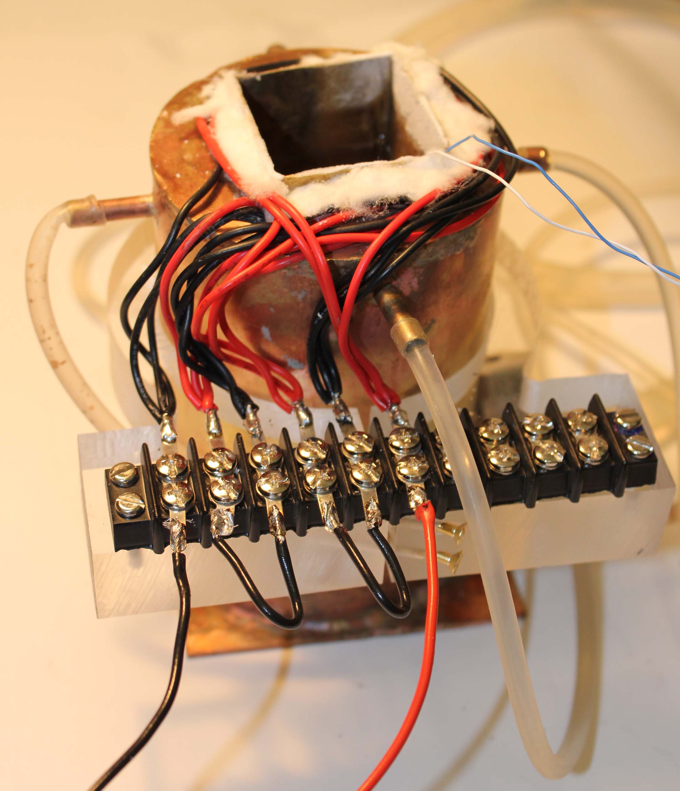
A length of 50mm square brass box section tubing A, was fitted with a brass plate, silver soldered in place at the lower end and soldered into a top plate, in turn soldered into a 3 inch diameter tube B, also closed at the lower end. Brass inlet and outlet pipes, D & E were fitted to permit a flow of water to course through the annular void between tube A & jacket B. The inside of tube A was lined with TEC1-12706 Peltier units, cemented to the inside walls and floor of A using Loctite 315 high thermal conductivity cement. An inner, square section brass vessel F was fashioned from 0.5mm brass sheet and silver soldered to form a leak-tight reservoir. This reservoir was a tight push fit between the Peltier units and lubricated using a thermally conductive silicone grease. A perspex block G was clamped to the exterior of A and fitted with a barrier connector strip H to which the fly leads from the Peltier units were secured. They were arranged in electrical parallel in groups of three and the groups were connected in series with a Hewlett Packard 6274B Power Supply. This was capable of delivering 15 amps at 60 volts if required and was programmable.
In use, the inner reservoir was filled with acetone and the outer jacket supplied with a current of mains water between 1 and 9 litres per minute. Current from the power supply was regulated between 4 and 13 amps.
The temperature of the acetone in the inner reservoir was measured using a Copper-Constantan thermocouple connected to a calibrated Comark electronic thermometer feeding a Yokogawa potentiometric recorder. The temperature of the outlet water was measured by a Mercury in glass thermometer readable to 0.1 deg C.
The variation of temperature in the inner reservoir with the total current supplied through the array of Peltier elements was determined for currents between 4 amps and 13 amps. Table 1 gives the results.

| Current | water t | cryostat t | Temp Diff | voltage | power |
| amps | deg C | deg C | deg C | volts | watts |
| 4.000 | 12.800 | -13.650 | 26.450 | 10.800 | 43.2 |
| 5.000 | 13.000 | -17.500 | 30.500 | 13.250 | 66.25 |
| 6.000 | 13.000 | -20.700 | 33.700 | 16.070 | 96.42 |
| 7.000 | 13.300 | -23.300 | 36.600 | 18.540 | 129.78 |
| 8.000 | 14.000 | -25.400 | 39.400 | 21.200 | 169.6 |
| 9.000 | 14.100 | -26.800 | 40.900 | 23.800 | 214.2 |
| 10.000 | 14.200 | -26.900 | 41.100 | 26.200 | 262 |
| 11.000 | 15.200 | -27.200 | 42.400 | 28.900 | 317.9 |
| 12.000 | 16.500 | -26.900 | 43.400 | 31.800 | 381.6 |
| 13.000 | 17.300 | -25.800 | 43.100 | 34.500 | 448.5 |
The data of table 1 is plotted in the adjacent graph showing reservoir temperature against current in blue, and total temperature difference against current in red. The water flow rate was 1.135 litres/minute. The minimum attainable temperature was -27.2 C with an outlet water temperature of 15.2 degrees. As expected, with currents in excess of about 11 amps, the heating contribution of the current offsets and exceeds the extra Peltier cooling the current provides. The red points in the graph show the total temperature difference which reaches a maximum at about 43 degrees at about 12 amps current.
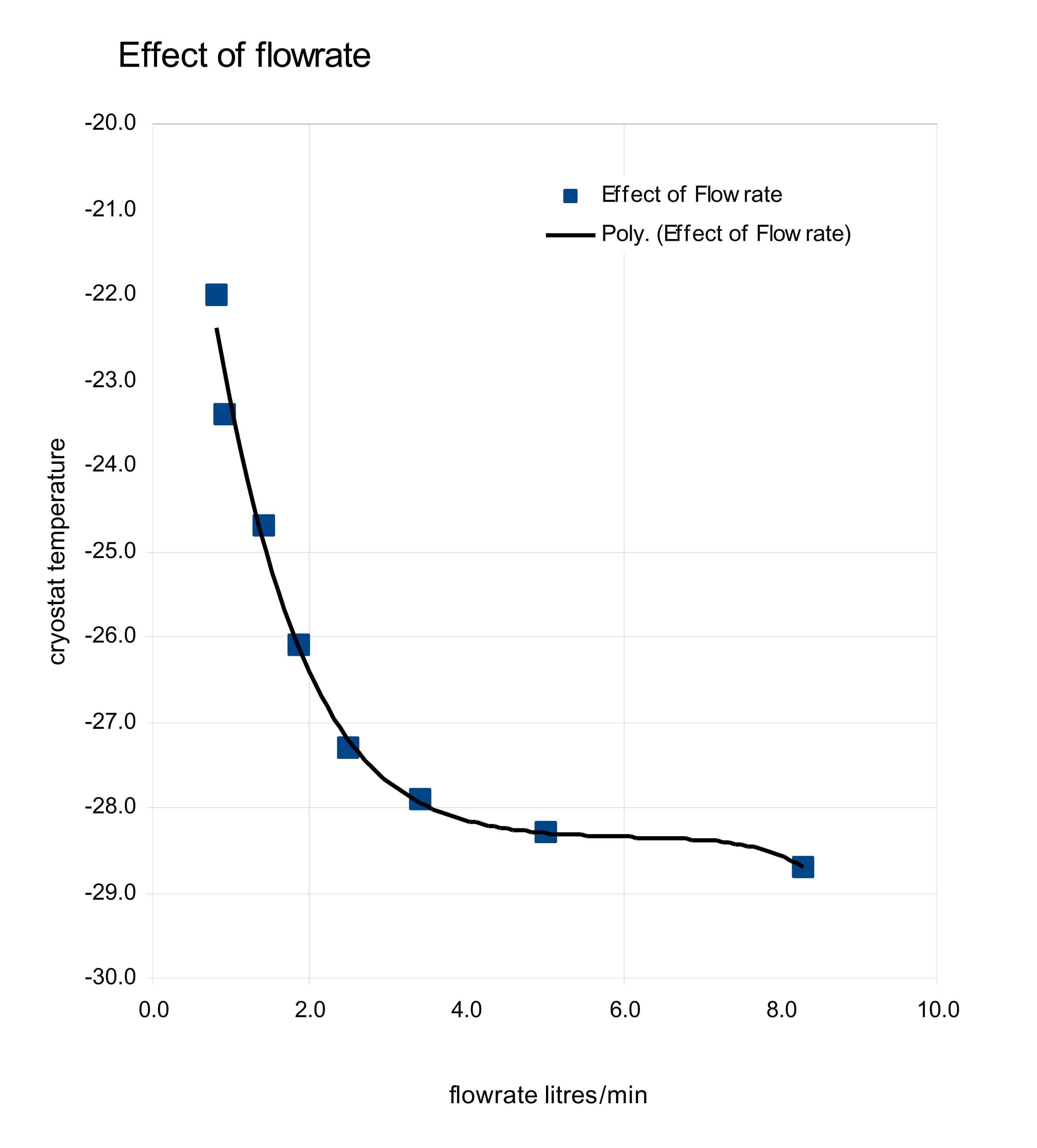
At constant current, the variation of the minimum attainable temperature with cooling water flow rate is shown in table 2.
| Flow rate | Tw | Tc | Temp Diff |
| litres/min | deg C | deg C | deg C |
| 0.824 | 17.200 | -22.000 | 39.200 |
| 0.925 | 16.600 | -23.400 | 40.000 |
| 1.415 | 14.900 | -24.700 | 39.600 |
| 1.875 | 14.400 | -26.100 | 40.500 |
| 2.500 | 13.800 | -27.300 | 41.100 |
| 3.409 | 13.300 | -27.900 | 41.200 |
| 5.000 | 12.900 | -28.300 | 41.200 |
| 8.300 | 12.700 | -28.700 | 41.400 |
As might be expected, the minimum temperature achievable at 9 amps current falls with increasing water flow rate, rapidly up to about 4 litres/minute and then only very slowly thereafter. The temperature of the cooling water has a direct effect upon the minimum achievable temperature, although adding extra cooling to water flowing at that rate would require a fairly large and costly plant.
With a flow rate set at 3.125 litres/minute, a further adjustment of the current, enabled the point of optimum performance to be determined. The results are shown in Table 3.
| Current | Tc | Tw | Temp Diff |
| amps | deg C | deg C | deg C |
| 10.0 | -29.4 | 13.0 | 42.4 |
| 11.0 | -30.2 | 13.4 | 43.6 |
| 12.0 | -30.7 | 13.6 | 44.3 |
| 13.0 | -30.8 | 14.0 | 44.8 |
Peltier Coolers are very energetically inefficient. Reference to table 1 will show that in the case under consideration, at the water flow rate of 1.125 litres/minute, little advantage in minimum temperature is to be gained by dissipation of more than about 200 Watts. However, at higher flow rates dissipations of up to 320 Watts can be justified in reaching a lower minium temperature. The cryostat as constructed did exhibit considerable capacity to remove heat: water in a test tube was fully frozen in less than a minute on immersion and very little change in the cryostat temperature was observed during the freezing process.