
ALL MATERIAL COPYRIGHT KEVIN SCOTT 2011. LINKS TO THIS SITE ARE WELCOME BUT DO NOT COPY MATERIAL FROM THIS SITE TO ANY OTHER WEBPAGE.


If you find this site useful, please support it by making a donation of $1 to help maintain and develop it. Click on the PAYPAL DONATE button to do this safely. But there is no obligation - please avail yourself of the information and facilities of the site at no charge.
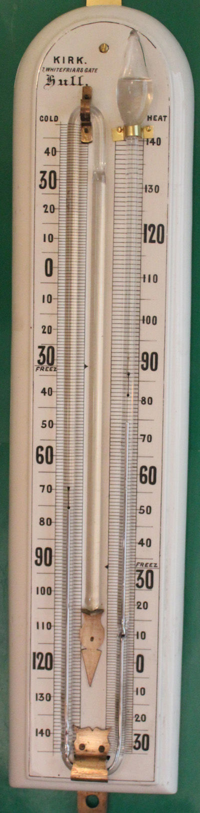
Six's maximum and minimum thermometers were the most successful traditional instruments to accomplish the measurement of the current temperature and the recording of the most recent maximum and minimum values at the same time. Invented in 1780 by James Six, the original form of the instrument was similar to that shown at the far right except that the movable indices were glass tubes with an iron core fitted with thin glass tails which. pressing against the wall of the thermometer restraining their motion. Clearly very great skill was required to make the instrument its original form
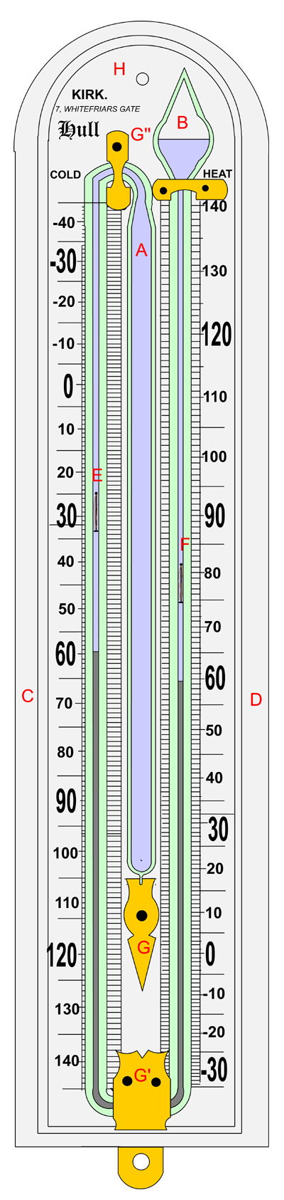
The version of Six's Maximum and Minimum Thermometer which is the subject of this study is shown diagrammatically to the right. It consists of a ceramic base H, supplied with the necessary scales, upon which is mounted the thermometer tube secured to the base by brass fittings, G, G', G'' etc. The tube itself has a reservoir A attached to a U tube in capillary glass terminating at its upper end with the expansion volume B. The lower extents of the U tube are filled with Mercury while the reservoir and the remaining upper portions of the U tube contain Ethanol. The two vertical limbs of the U tube carry indices which are pushed upwards by the rising mercury level, but retain their vertical position when the mercury recedes. The construction of the indices from iron wire allows them to be repositioned to the Mercury meniscus at will, by means of a magnet.
With the correct volume of Ethanol in reservoir A, matched to the bore of the U tube, so that the expansion of the Ethanol results in the correct advance of the mercury thread with increasing temperature, the instrument functions as a standard liquid-in-glass thermometer, with the current temperature indicated on the left hand scale by the descending mercury meniscus and similarly on the right hand scale by the ascending Mercury meniscus. Additionally any upward movement of the Mercury meniscus on either side bearing upon one of the moveable indices, will drive that index upwards. Thus the minimum temperature reached in any measurement period will be recorded by the left-hand index, while the maximum will be indicated by the right hand index.
The design and construction of the indices is the most critical aspect in the manufacture of a Six's thermometer. What is required is that the index moves freely when driven upward by a rising mercury meniscus, but retains its position at all other times. except when being restored to the Mercury meniscus by means of a magnet. It must be secured sufficiently well not to slip down the tube under the influence of gravity, nor secured so strongly that a rising meniscus of Mercury forces its way past the index, nor be so secure that the operator's magnet is unable to reposition it.
The degree of restraint required to avoid these extremes has been achieved in at least four different ways:
(a) As we saw above, the original instrument by Six restrained the movement of the glass-sleeved indices by attaching to them, thinly-drawn glass filaments which, in contact with the bore of the thermometer tube, provided a frictional restraint of the correct magnitude.
(b)Other versions of the thermometer rely on the springiness of the index itself to provide the restraint. This involves putting a slight bend in the index stem. It is difficult to get this exactly right and it is possible that the springiness of the index might change over time, rendering the performance of the thermometer of questionable life.
(c) In the design of the instrument under discussion here, the indices were restrained by the use of several strands of horsehair attached to the upper end of each index. These hairs tended to lie against the glass bore and provided a restraint derived from surface tension. The real advantage of this method over (a) & (b) above, is that it requires no subtle or individual adjustment of the springiness or curvature of any component of the index. The restraining force is independent of any such manipulation and can be approximately controlled by the number of hairs attached to each index.
(d) Modern Six's thermometers have an even simpler method of restraining the motion of the indices. A magnetic plate is mounted behind the thermometer so that the indices are always attracted by it to the rear surface of the thermometer bore. They still move with the mercury, but are held otherwise stationary by the magnetic plate. When a button is pressed by the user, the magnetic plate is pushed away from the thermometer sufficiently to allow the indices to descend to the current positions of the Mercury meniscuses.
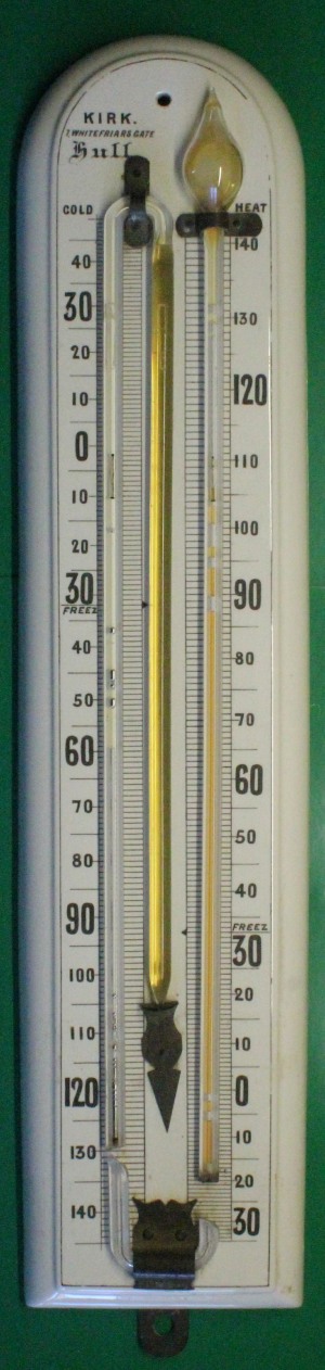
The instrument as received for repair is shown to the left. As can be seen the capillary U tube is broken at the lower end, most of the mercury has escaped and from its condition, it appeared that a considerable time has elapsed ( perhaps several years) since the thermometer was broken. The retrieval of the indices was attempted, but the effects of corrosion were such that they disintegrated upon removal. They thus needed to be replaced. Apart from crazing to the glazing the ceramic base seemed in good condition. The brass fittings were heavily corroded and the top fitting was missing and required replacement. The glass parts were all soda or lead glass and because capillary in this size is no longer available in small quantities in soda glass, it was resolved to replace the glass construction with a copy in borosilicate.
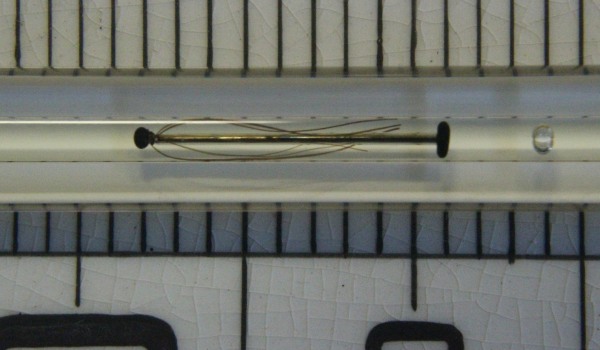
The photograph above shows the structure of the indices in the original instrument. Reproduction of these proved somewhat more of a challenge than first thought. The index consisted of four components: A thin steel piano wire (possibly lacquered), a bead at the upper end and a disk shaped foot at the lower, and a number of horse hairs attached to the upper end. The foot was possibly ebonite, and was attached to the wire by some form of cement which had degraded so that the union between these parts was not secure.
It was first thought possible to fashion a new foot from an epoxy putty or from an epoxy resin, but neither of these options proved successful, because standard epoxy (e.g. Araldite) degrades under ethanol. This was observed by testing an index constructed with Araldite by submersion in ethanol for 1 month. After this period, the araldite was found to be soft and disintegrating. The susceptibility of Araldite to ethanol, also had the effect of rendering the resin liable to stick to the glass under ethanol.
An ethanol-resistant epoxy, is, however, available. Masterbond manufacture a grade of epoxy, EP41S-1HTND, which has all the necessary properties to bond steel and horsehair while yielding a bond entirely resistant to ethanol. The price is too high to justify for the repair in question but is otherwise entirely justifiable given the research that stands behind it. But for the present task a much cheaper solution had to be found. It so happens that an ethanol resistant epoxy is available for rendering motorcycle fuel tanks resistant to the new ethanol component in the fuel. C Wylde & Son Ltd supply a two part epoxy intended to line fuel tanks. This proved admirably suited to the present application and was tested by soaking in ethanol at 80 C in a sealed tube for 8 days. (This is approximately equivalent to 240 days at room temperature.) No degradation was observed. To match the original, the epoxy was mixed on a microscope slide, previously covered in lampblack from a candle flame. Mixed in this way, the epoxy set to a shiny smooth pitch black, which was found well-suited to the task of retaining the horsehair in the form of a small bead attached to the top of the index shaft. The latter was a 15mm length of 0.35mm diameter piano wire.
The final procedure for making the indices was as follows:-
a)15mm of 0.35mm diameter piano wire was cut to length.
b) a bead of the epoxy, approximately 1 mm in diameter was attached to one end of the wire and allowed to set at room temperature and then baked at 60 C for 3 hours.
c) A bunch of 6 fine horse hairs was wetted and threaded into a 3 mm length of PVC tubing 0.5mm ID 0.25mm wall.
d)The piano wire was also threaded into the PVC tube and the ends of the horse hairs were trimmed to be level with the unbeaded end of the wire.
e) Epoxy resin, mixed on a microscope slide, previously coated with lampblack was applied to the trimmed end of the wire to secure the horse hairs and to form a small bead to terminate the wire. This was allowed to set at room temperature and then baked at 60 C for 3 hours, to render it hard and smooth.
f) Excess horsehair was trimmed from the index.
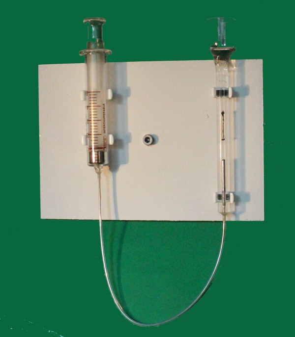
Prior insertion into the new thermometer tube, the indices were tested using the simple arrangement in the photograph below, left. A standard 5 ml glass syringe was connected to a section of 1.6mm bore capillary with a wider glass tube sealed to its upper end. Mercury was introduced into the capillary and drawn, in part, into the syringe and the remaining section of capillary filled with ethanol. The index to be tested was introduced into the capillary and the syringe plunger used to simulate the movement of the mercury. Tests were carried out to ensure:
a) that the Mercury had no difficulty in raising the index and had no tendency to flow past it.
b) that the index did not slip down the tube when left in a position away from the mercury meniscus, and
c) that the index could be restored easily to the top surface of the mercury using a magnet.
When the damaged thermometer was opened, the thermometric fluid smelled phenolic, signifying that an oxidation inhibitor had been added to the ethanol, to prevent rusting of the indices. It was not possible to determine easily exactly the chemical constitution of the inhibitor, but it was resolved to add to the replacement ethanol, 5% by weight of 2,6, Di-tert-butyl -p-cresol which is a non-toxic antioxidant.
The average distance per degree Fahrenheit on the scale of this instrument was found to be 2.06mm/deg F. Along the length of the scale and comparing both sides, there was found to be considerable variation in this calibration distance at different points on the scale. Although there is slight non-linearity in the thermal expansion of alcohol, the variations on the scale are too greater to be accountable by this. It is probable that the scale has been inaccurately ruled during manufacture. The only available course of action is to take an average value.
The volumetric thermal expansion coefficient of ethanol is 0.000416 deg F-1. With a tube bore of 1.6mm, the expansion volume per deg F = 4.15 mm3. The required volume is thus 9.96 ml. With a reservoir length of 295mm, the internal diameter of the reservoir must be 6.55mm.
The procedure for constructing the thermometer tube is as follows:
a) A 295mm length of 6.55 mm bore borosilicate tubing 8.9mm OD is cut and the end sealed leaving a short glass nipple for the retaining bracket G. This forms the reservoir.
b)The open end of the above tube is sealed to a 1 metre length of 1.6mm bore borosilicate capillary tube.
c)The capillary tube is bent to a tight U adjacent to the reservoir.
d) The index for the minimum limb is inserted in the open end of the capillary, with the horsehair retaining bead in first, and, using a magnet, the index is positioned about 150mm from the U previously formed. It is important that some of the horsehair strands are made to lie above the index, otherwise the index will not be retained in a static position within the bore. Using a magnet secured to the tube with adhesive tape, the index is retained in this position.
e) Two right-angle bends are now made in the capillary tube to form the wide U at the lower end.
f)A bulb is blown in the shape of the expansion chamber A at the end of a conveniently sized borosilicate tube and one side of the bulb is flattened to produce a semicircular cross-section. The tapered top of the bulb is opened and a 4mm OD borosilicate tube sealed on to it for temporary use in the filling process.
g) The capillary tube is cut to length and the bulb produced by process (f) is then sealed to the open end. This completes the glass-blowing.
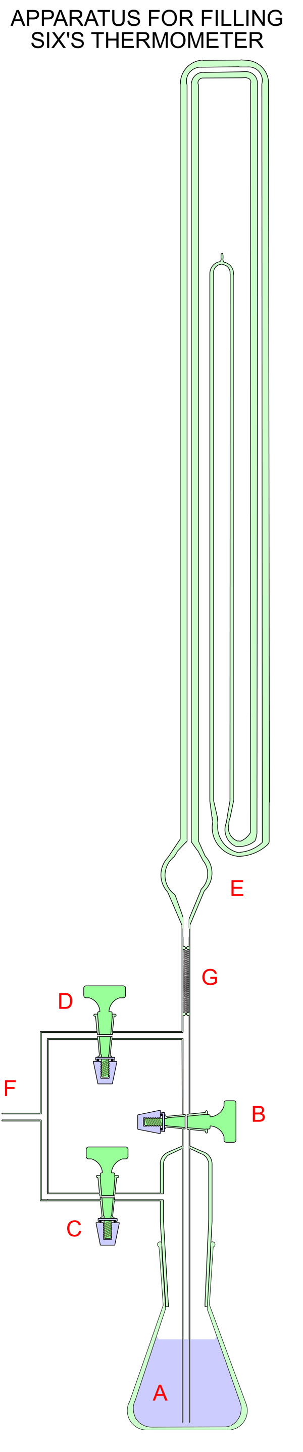
A suitable apparatus for filling a Six's thermometer is shown at the left. This is used in the first stage of filling in which the entire thermometer is filled with Ethanol/substituted p cresol mixture. The sequence of operations is as follows:
a) All the taps are closed. Vacuum is applied to outlet F.
b) Tap D is cautiously opened to evacuate the Six's thermometer tube. Care must be taken not to disturb the minimum index which is in place and secured by a magnet. Large sudden outflows of air might cause the index to move rapidly along the tube and forced into a bend in the glass or otherwise damaged. The risk of this is reduced by restriction G which contains 200 mesh alumina to prevent rapid flows of wither air or liquid into of out of the thermometer tube.
c) The Six's thermometer tube is left under continual pumping for 30 minutes to remove any residual moisture.
d) Tap D is closed and tap C is cautiously opened to remove dissolved gases from the thermometric fluid in A. This will involve some effervescence which can be controlled by the dexterous use of tap C. Eventually the surface of the alcohol will become still and tap C can be closed.
e) Tap D is opened for a minute to ensure that the vacuum in the thermometer tube is as high as possible, and closed.
f) The vacuum is disconnected from F which is allowed to be exposed to the atmosphere.
g) Tap C is opened to allow atmospheric pressure on to the fluid in A.
h) Tap B is now opened cautiously to allow the fluid to fill the thermometer tube. If the vacuum is sufficient (< 1mB) the fluid will completely fill the tube without any air bubbles.
i) The thermometer tube is now removed from the filling device by cutting the stem above the junction with Tap D.
j) The next task in the filling operation is to remove some of the thermometric fluid from the outermost limb of the thermometer tube. This can be carried out using a length of 500mm of fine Teflon tube (0.35mm bore, 0.35mm wall) attached to a hypodermic syringe. This device can be realised by first etching the end of a suitable piece of Teflon tubing using Sodium naphthalenide in tetrahydrofuran, and then cementing the etched end into the outlet of a glass hypodermic syringe using a epoxy resin. (Details of this procedure can be found here.)
k) A little more than half the fluid in the outer limb of the thermometer tube is removed, and then using the same teflon tube/syringe device, approximately 0.9 ml of clean mercury in added. This is a slight excess over that which will finally be required.
l) The thermometer should now be allowed to stand for 1 hour in a constant temperature, which should be measured by a separate, accurate instrument.
m) The teflon tubing is fed into the thermometer tube, through the mercury, around the lower U into the middle limb. Care must be taken that no air bubble is introduced in this process.
n) Alcohol is then withdrawn until the level of the mercury in the minimum (left hand) limb indicates the correct current temperature.
o) The teflon tube is withdrawn to the right hand limb and mercury removed until its meniscus indicates the same temperature as the left hand limb. The teflon tube is then fully withdrawn.
p) The second index is then installed in the right hand limb.
q) Most of the alcohol is now removed temporarily from the right hand limb, and a narrow constriction made in the glass tube just above the expansion chamber. This will facilitate the final sealing of the instrument.
r)The alcohol is replaced to a level such that the expansion chamber is about half-full of liquid, and the constriction sealed.
The filled thermometer tube is now aligned on its ceramic mount and the brass fittings replaced. Care must be taken to ensure that no part of the glass is under any significant strain when the screws are tightened and some adjustment to the mounting hardware may be necessary to achieve this.
The completed thermometer is allowed to stand vertically for several days to verify correct performance of the maximum and minimum indices.