
ALL MATERIAL COPYRIGHT KEVIN SCOTT 2011. LINKS TO THIS SITE ARE WELCOME BUT DO NOT COPY MATERIAL FROM THIS SITE TO ANY OTHER WEBPAGE.


If you find this site useful, please support it by making a donation of $1 to help maintain and develop it. Click on the PAYPAL DONATE button to do this safely. But there is no obligation - please avail yourself of the information and facilities of the site at no charge.
On this page, passing the cursor over the diagram below will generate a magnifier to observe details of the drawings. Using the mouse wheel the magnification can be varied. To give sufficient resolution to make the drawings useful, they need to be fairly large files and will take a few moments to load.
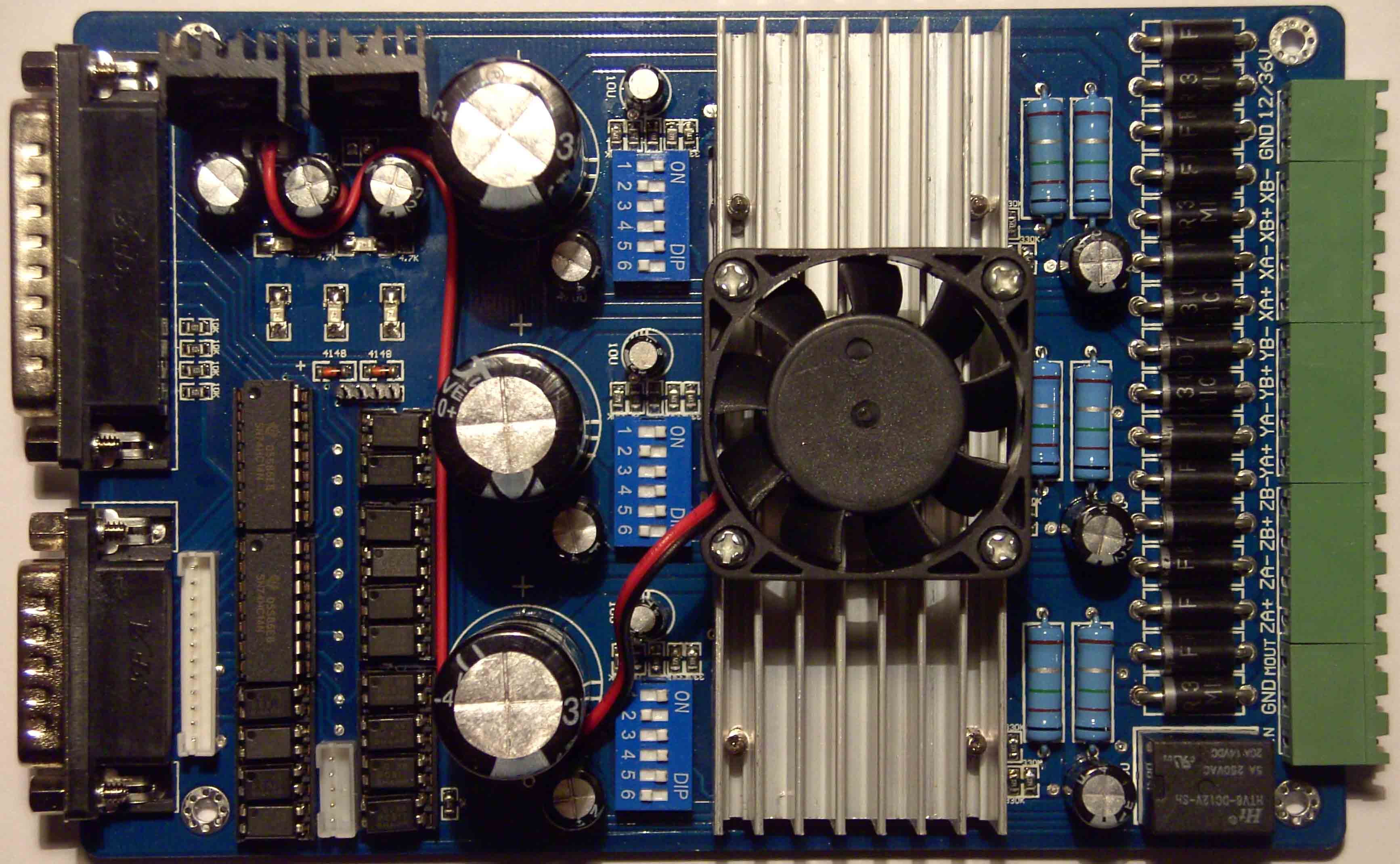
The photograph above shows a generic 3-axis stepper controller board designed round the TB6560 controller/bridge driver from Toshiba. Regrettably, although purchased new, it was supplied with no data except for the TB6560 datasheet. Probably used via the parallel port under the CNC control software Mach 3, it would have worked satisfactorily, but it was required to interface to an embedded PC via a General Purpose I/O port, so the pin definitions were essential. The simplest way of getting these was by reverse engineering the PCB, and the results of this process are published here. The Schematic obtained by careful visual inspection and by continuity tests is shown below. The image has sufficient resolution to provide the necessary information to the user of the board, but, even with the help of the magnifying cursor, may not be studied very easily on the screen. Accordingly, the PDF of the drawing can be downloaded here, or the full size image examined in via a web page here. The datasheet for the TB6560 can be downloaded here
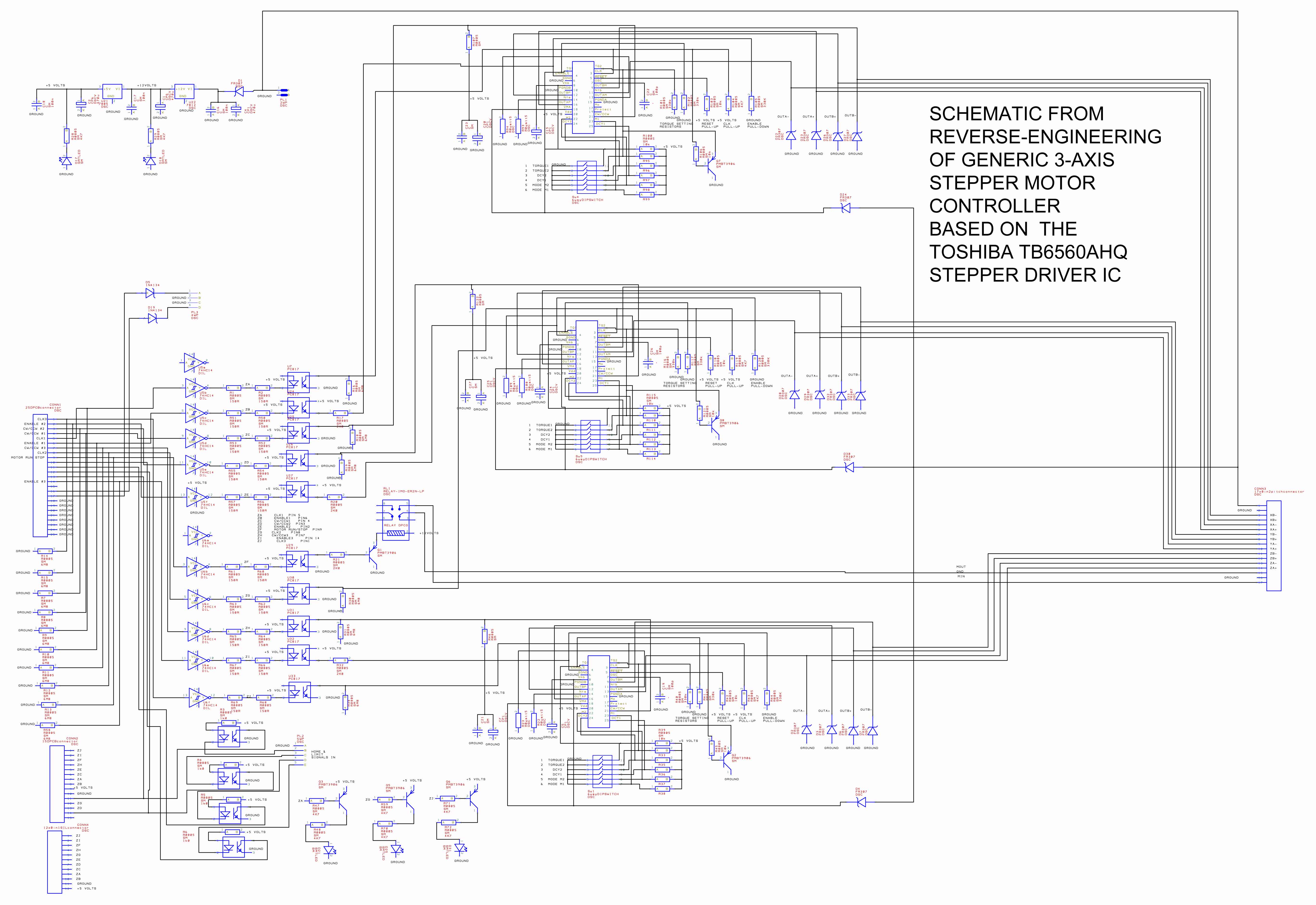
The circuit is conventional. Control signals from the parallel port are applied to the 8 bit wide bus and in addition, some bi-directional control lines
are also used. Four lines are used to return homing or limit switch information back to the host computer. The four limit switches can be attached
to connector PL2 and are active low.
The input lines are pulled down by 6.8M resistors, probably intended to provide some anti-static resistance. All traffic to and from the parallel
port is optically isolated by a combination of the 74HC14 inverters and thePC817 opto-isolators. Thereafter the signals are applied to the enable, clockwise/counterclockwise,
and clock controls of the three TB6065AHQs. Other options are selectable in hardware via the DIP switches which are controlled as follows:
| MOTOR CURRENT | SWITCH 1 | SWITCH 2 |
| 100% | ON | ON |
| 75% | ON | OFF |
| 50% | OFF | ON |
| 25% | OFF | OFF |
| DECAY MODE | SWITCH 3 | SWITCH 4 |
| FAST | ON | ON |
| 25% DECAY | ON | OFF |
| 50% DECAY | OFF | ON |
| 100% DECAY | OFF | OFF |
| MICROSTEPPING | SWITCH 5 | SWITCH 6 |
| 1 | ON | ON |
| 1/2 | ON | OFF |
| 1/16 | OFF | ON |
| 1/8 | OFF | OFF |