
ALL MATERIAL COPYRIGHT KEVIN SCOTT 2011. LINKS TO THIS SITE ARE WELCOME BUT DO NOT COPY MATERIAL FROM THIS SITE TO ANY OTHER WEBPAGE.


If you find this site useful, please support it by making a donation of $1 to help maintain and develop it. Click on the PAYPAL DONATE button to do this safely. But there is no obligation - please avail yourself of the information and facilities of the site at no charge.
Commercially available Pirani gauges seem to be unnecessarily expensive. The basic design consists of a simple coil of wire exposed to the vacuum to be measured and connected as an arm of a Wheatstone bridge, with a meter reading the out-of-balance voltage of the bridge. With suitably chosen components, the out-of-balance voltage can vary with the pressure from about 10mB down to 0.001 millibars. Although commercial versions, albeit with some extra sophistication, can cost over $2000, the instrument described here can be constructed for one hundredth that sum and prove as useful in the laboratory as its more expensive cousin.
If a wire, surrounded by a gas, is heated electrically, heat is lost from it by three processes: radiation, conduction and convection. The first of these is independent of the pressure of the gas and cannot therefore contribute to its measurement although it gives rise to a constant loss of heat. Convection contributes significantly at high pressures, but the heat loss caused by it is not proportional to the pressure and in the ideal case, is independent of it. Conduction of heat by an ideal gas is proportional to the pressure over a range approximately lying between 10-5 mB and 10-2 mB. In practice, the variation of heat loss from a hot wire with pressure can be exploited between 0.001 mB and 10 mB. The instrument described here operates in this range.
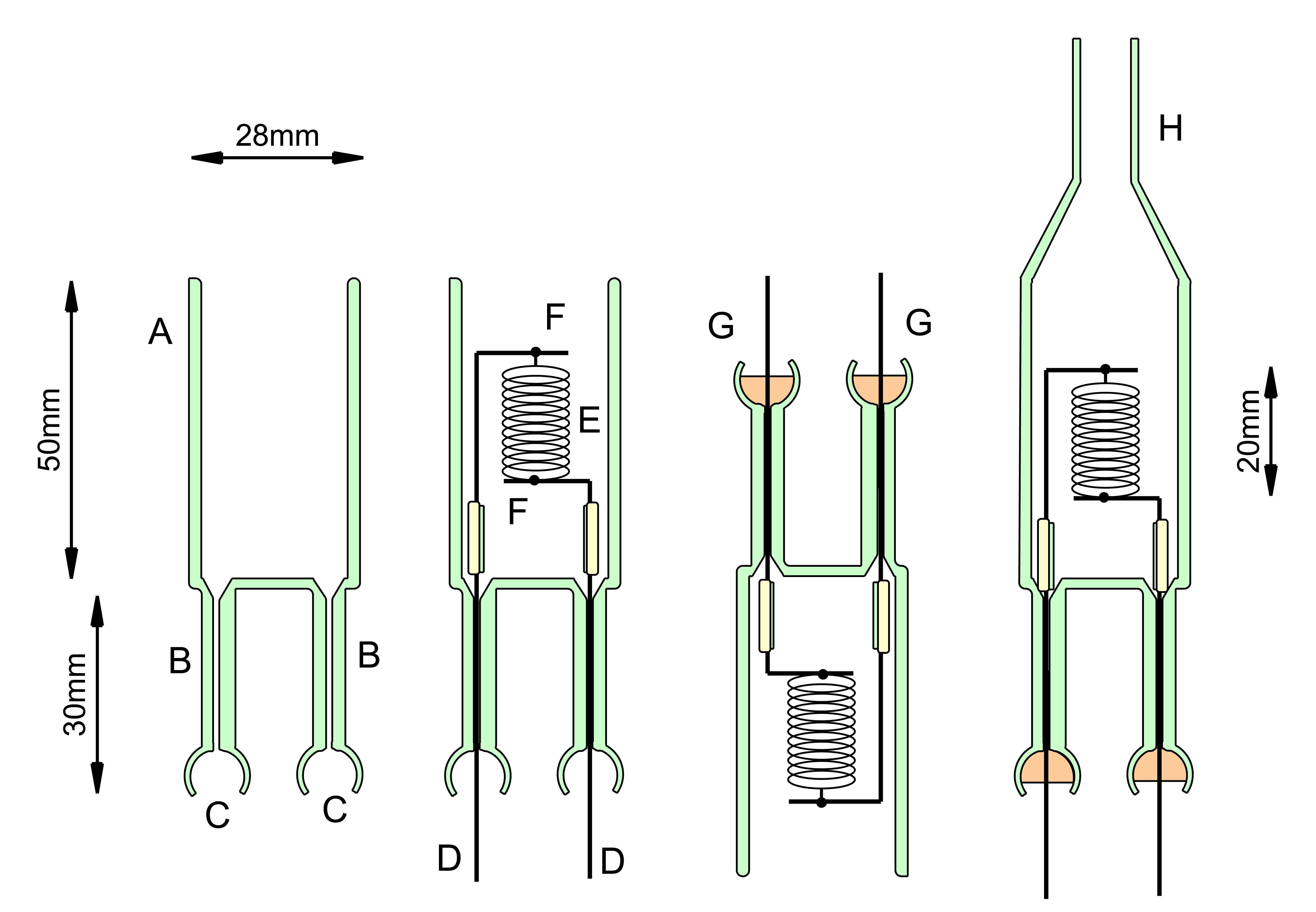
The construction of the Pirani gauge head is shown on the right. A glass envelope of diameter 28mm is provided with two 1 mm bore capillary inlets with wide openings as shown. A filament structure comprising 0.7mm diameter stainless steel wire supports F, welded to a stainless steel wire coil E ( 0.1mm diameter wire, 56cm in length, wound in an open helix diameter 8mm, resistance at 20 C of 24.6 ohms) was supported by a short length of glass tube to which the 0.7mm wires were cemented using Ceramabond 569 (Aremco Products Inc). The 0.7mm SS wires were cemented into the capillary tubes using Araldite standard Epoxy. ( Separate experiments were conducted to examine the quality of seal produced in this way. By applying vacuum, the resin could be drawn down the capillaries for about 20 mm prior to hardening. It was found that cured seals made in this way were sound at least to 10-5 mB pressure. A high vacuum epoxy is available which is capable of sustaining a vacuum of 10-9 mB, but this was considered un-necessary in the present application.) After hardening the epoxy, the 28mm tube was drawn down as shown and fitted with an inlet tube of 6mm OD.
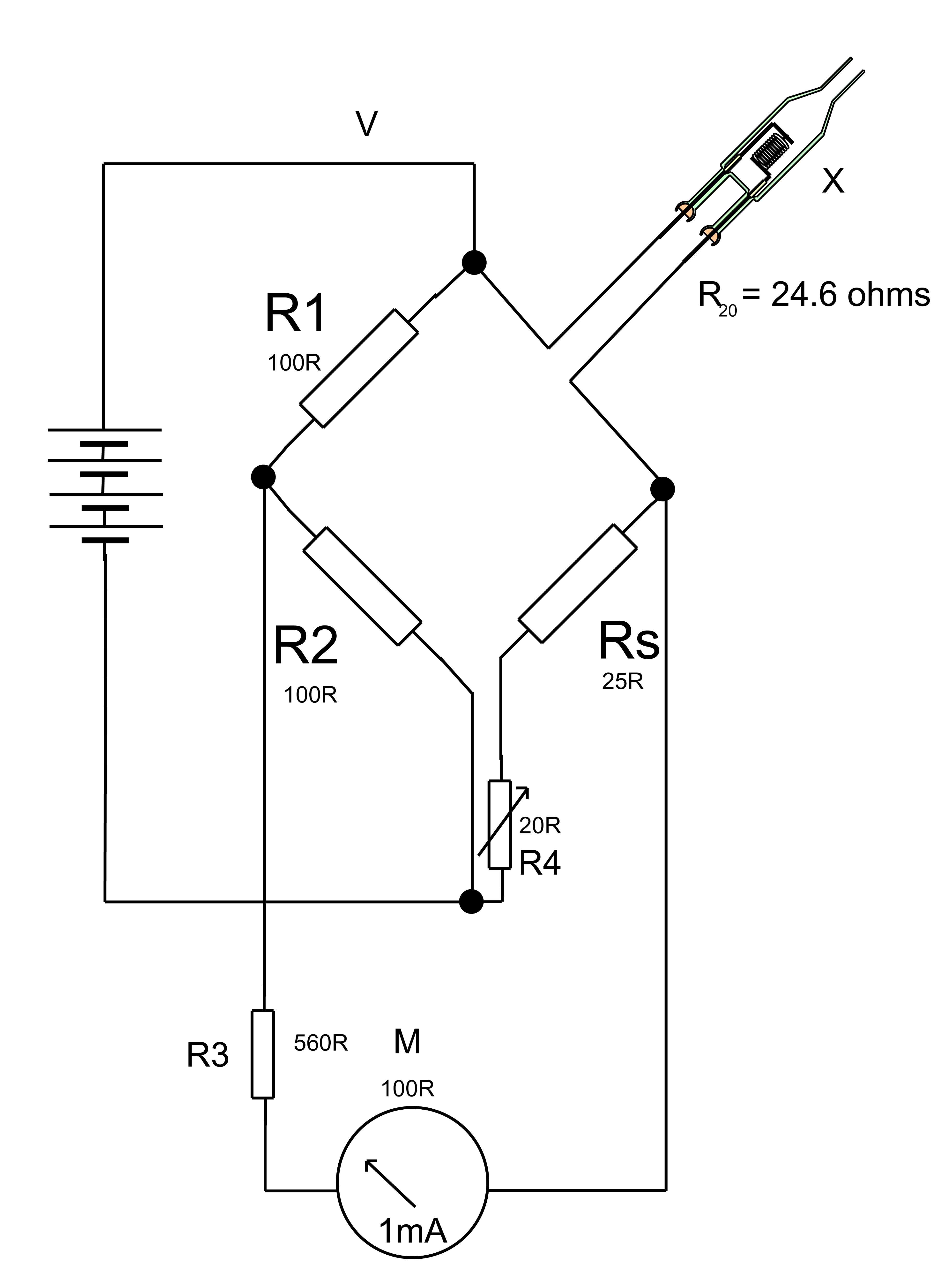
There are three modes of operation for a Pirani gauge: (i)constant current, (ii)constant resistance and (iii)constant voltage. The first is termed the Pirani-Hall Gauge and involves feeding the wire filament with a constant current and measuring the voltage across it, which increases with falling pressure as the temperature of the wire increases. Option (ii) requires the incorporation of the filament in a micro-calorimetric bridge such that the current is varied automatically to keep the bridge balanced and the product of the voltage and filament current are used to compute the power dissipation which is approximately proportional to the pressure over the usable range. This measurement mode is capable of the best precision, but involves more complicated electronics and some computation to exploit it. Option (iii) is the best for general purpose use and requires only very simple electrical circuitry as the diagram shows. R1 & R2 are 1 watt 100 ohm resistors which form the reference arm of the bridge. Rs & R4 complete the bridge and R4 is adjusted to give 0.66V out of balance voltage when the gauge is at 1 atmosphere pressure. This represents the lowest wire temperature. As the pressure is reduced, the filament temperature rises to about 500 degrees C at 0.001 mB, and the out of balance voltage indicated by the meter falls to about 0.07V.
With the values of components shown in the schematic, Out of balance voltages were measured against pressure using a Vacuum Generators Pirani gauge type PIR 1A. The data are shown in the table:
| PRESSURE | Vbridge | percent FSD | log pressure |
| mB | mV | ||
| 1000 | 660 | 100 | 3 |
| 7 | 570 | 86.36 | 0.8451 |
| 2 | 400 | 60.60 | 0.3010 |
| 0.4 | 340 | 51.51 | -0.3979 |
| 0.2 | 260 | 39.39 | -0.6989 |
| 0.1 | 210 | 31.82 | -1 |
| 0.09 | 195 | 29.545 | -1.045 |
| 0.08 | 185 | 28.03 | -1.0969 |
| 0.06 | 165 | 25 | -1.2218 |
| 0.059 | 157 | 23.788 | -1.2291 |
| 0.027 | 118 | 17.87 | -1.5686 |
| 0.036 | 125 | 18.93 | -1.443 |
| 0.010 | 110 | 16.7 | -2 |
| 0.005 | 105 | 15.9 | -2.3010 |
| 0.003 | 90 | 13.636 | -2.522 |
| 0.001 | 70 | 10.606 | -3 |
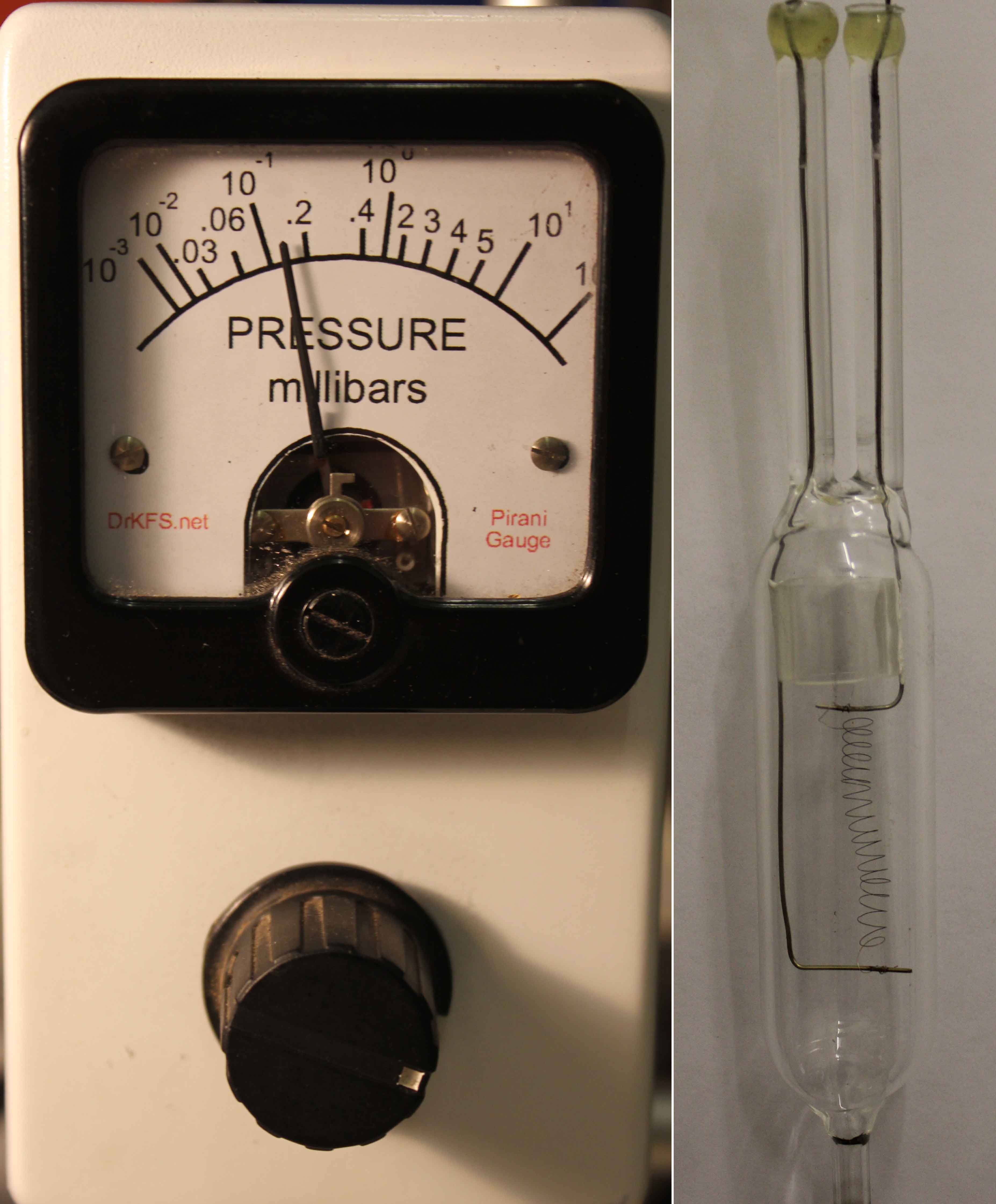
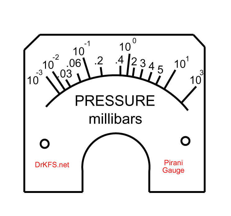
If identical values of components are used and the specifications of the Pirani gauge head are carefully followed, the data in the above table can be used to produce a calibrated scale for the 1mA meter. Below is a drawing of such a scale In use the adjustable resistor R4 is set to give the meter reading as FSD at 1 atm pressure before pumping down the gauge.
 Comparison with the commercial Vacuum Generators Pirani Gauge and with a McLeod gauge showed that the instrument constructed indicated a pressure within a factor of 2 of the pressures measured with the other instruments across the range.