
ALL MATERIAL COPYRIGHT KEVIN SCOTT 2011. LINKS TO THIS SITE ARE WELCOME BUT DO NOT COPY MATERIAL FROM THIS SITE TO ANY OTHER WEBPAGE.


If you find this site useful, please support it by making a donation of $1 to help maintain and develop it. Click on the PAYPAL DONATE button to do this safely. But there is no obligation - please avail yourself of the information and facilities of the site at no charge.
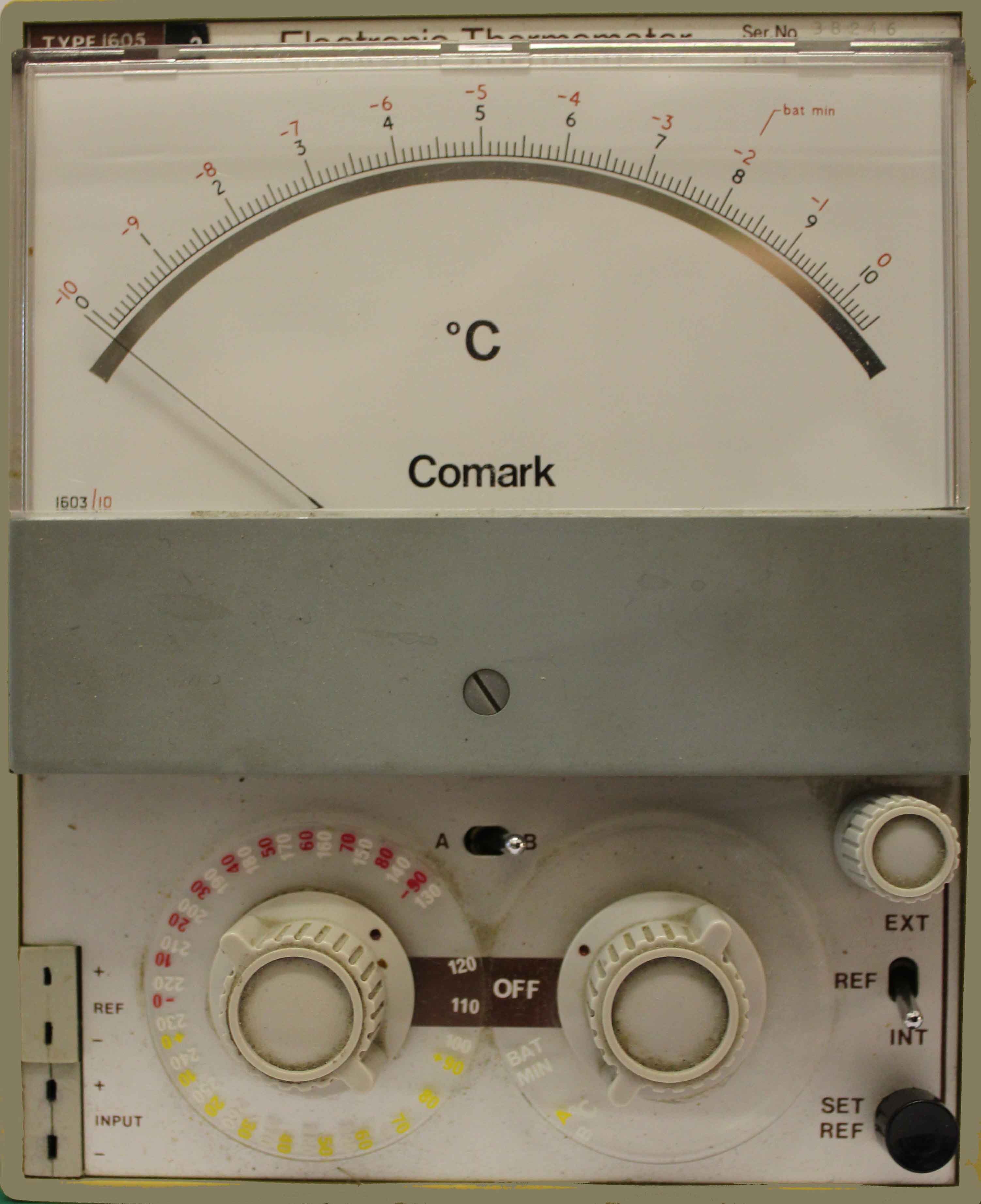
This page is devoted to the Comark Analogue Thermocouple meter series which dates from the 1960s -1980s. These instruments are no longer manufactured but are reliable and capable of high precision and can still be purchased on the second-hand instrument market. They were very expensive when introduced because they contained an ingenious chopper amplifier realised with germanium transistors which gave very high DC gain. Before the advent of operational amplifiers, high DC gain was difficult to achieve using discrete transistors, but the original Comark Company (of Littlehampton, Sussex, England) built its business on the invention.
The original Comark Company was taken over in the 1990s and then again by Fluke more recently and the present company has no record of these early analogue instruments.
The type of instrument can be determined from the model number. The third digit indicates the thermocouple type: 0 = Chromel Alumel (Type K), 2 = Copper Constantan (Type T), 4 = Iron/Constantan (Type J).The fourth digit indicates the range configuration: 1 = -87 deg C - 1000 C in 4 ranges, 8 = 0 - 400°C in 40 ranges (allowing any 10 degree range to be displayed on the meter).
Comark also made a range of microvoltmeters and multimeters: the Model 1201 is an electronic multimeter and the Model 1221 is a microvoltmeter.
The following is reproduced from a partial instruction sheet:
The Electronic Thermometers of Group 1 each have four ranges - one for temperatures below zero and three for temperatures above zero. The positive ranges start from zero and are desensitised to give increased coverage; the negative range uses a simple backing off circuit.
A number of custom-built instruments are similar to Group 1 thermometers; the differences are listed on a special manual sheet, specific to the instrument type concerned.
Each instrument has 3 structural units:
UNIT 1 (Front): This unit determines the type of instrument. It contains four sub-assemblies:
D.C Power Stabiliser
D.C. Amplifier board,
Switch Assembly,
Meter.
UNIT 2 (Case) The case and fittings are structural parts and no servicing should be required.
UNIT 3 (Rear) A number of different rear units are available, including battery or AC mains power supply, multiple thermocouple switching units etc.
| Thermocouple Material | Instrument Type | Ranges | Accuracy at 23°C | Cold junction deviation | Resolution per division |
| NiCr/NiAl | 1601 | -87 to 25°C 0 - 100°C 0 - 300°C 0 - 1000°C | +/- 2% FSD | +2°C | 2°C 1°C 5°C 10°C |
| Cu/Con | 1621 | -60 to 10°C 0 to 60°C 0 - 180°C 0 - 400°C | +/- 2% FSD | +2°C | 1°C 1°C 2°C 10°C |
| Fe/Con | 1641 | -65 to 20°C 0 to 78°C 0 - 240°C 0 - 730°C | +/- 2% FSD | +2°C | 2°C 1°C 5°C 10°C |
1. Connect the thermocouple to input. Verify the correct polarity.
2. Switch right hand rotary switch to 'bat min and check that the meter pointer is above 'min'. Switch to °C.
3. Switch left hand rotary switch to positions A, B, C, or D to obtain the largest on-scale pointer deflection. Read temperature on the appropriate temperature scale.
4. Output + 1 Volt d.c. at full scale deflection, 2mA maximum from sockets on the side to the right of meter. The output must be isolated from the thermocouple. Output resistance 500 ohms. This output can be fed to the input of a Comark Series 4000 Recorder.
Use the correct thermocouple type.
Before switching on, check that the meter pointer is at the '0' mark. Adjust zeroing screw with a screwdriver if necessary.
Do not operate the instrument in a draught.
Extend thermocouple leads with compensating leads only.
When out of use for long periods, remove the batteries.
Batteries - Remove screws on rear cover. Use leak-proof cells of the correct type only. Verify polarity.
•
AC Powered Models - To change line voltage, remove screws on rear cover, Solder red covered link to pin corresponding to line voltage required (11OV/230V) , accessible through rectangular cut-out in back panel.
Selector Unit » Connect the inputs to the terminal strip on the rear; each channel is fully isolated. Select the required input with right hand rotary switch. Front panel input may only be used when there are no thermocouples connected to the rear terminal strip.
Temperature Trip - Select the required temperature range with the left hand rotary switch. Set right hand rotary switch to 'Set Trip' and adjust central control until the pointer indicates the required trip temperature. The relay contacts are accessible on a terminal strip on the rear of the instrument. ^Hl' contacts close at trip temperature. Contacts fail safe to high for power failure or open circuit thermocouple. The trip circuit does not affect the normal operation of the instrument.
Dual Temperature Trip - Set the first trip temperature as above, Set right hand switch to Set Trip B and adjust right hand variable control until the pointer indicates the required trip temperature.
Group 1 instruments should be recalibrated after repair work has been carried out and it is advisable to check calibration every six months to compensate for ageing of components. The procedure given will bring the instrument within specification on all ranges. By modifying the calibration routine it is possible to obtain better accuracy on any one range, but other ranges may then be out of specification.
Precision d. c. voltage source and potentiometer (to give outputs from 0 to 50mV resolved to 1μV)
backing-0ff supply (0-3mV)
Thermocouple tables or the calculator on the right of this page.
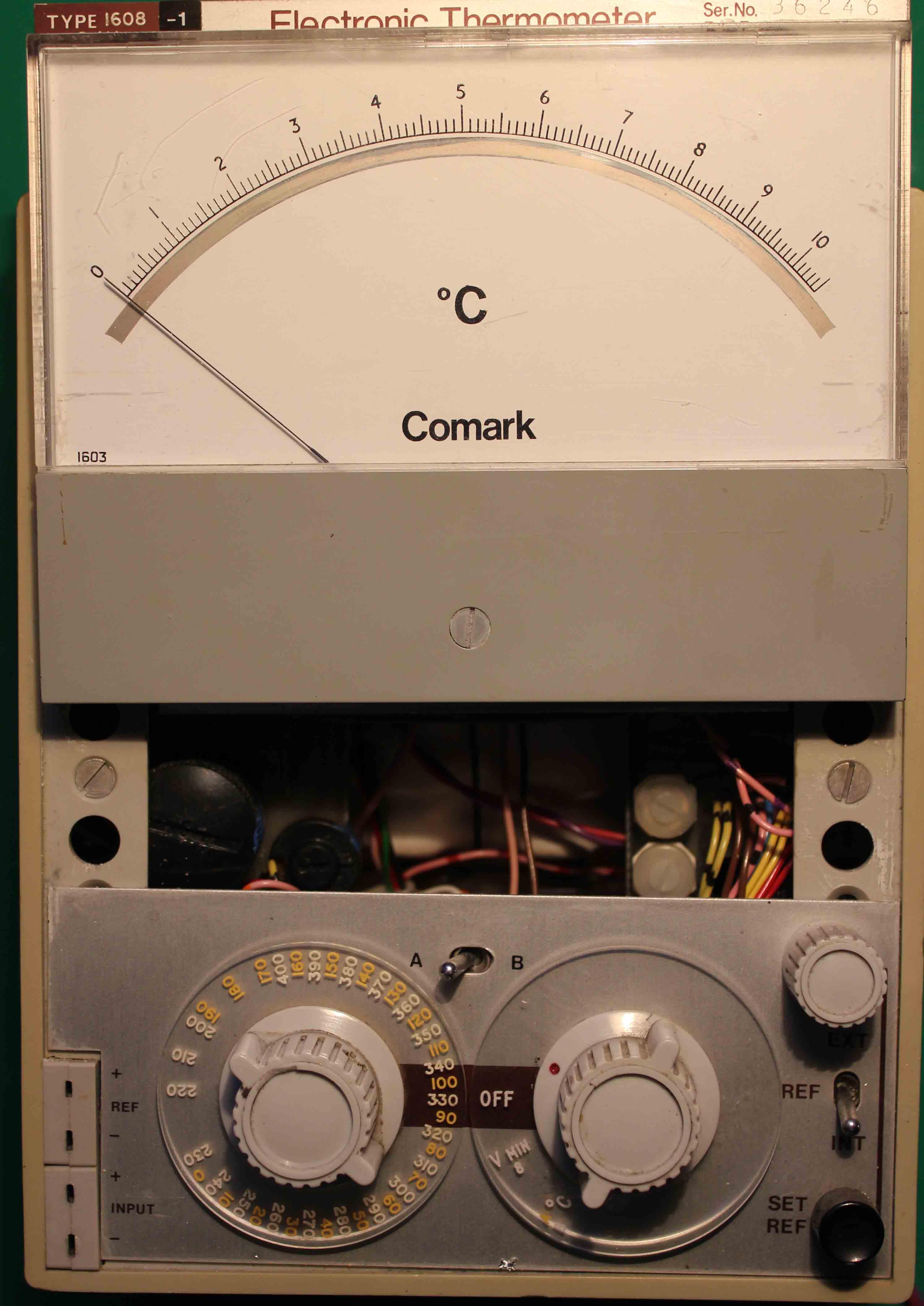
The calibration controls are mounted behind the front panel and may be reached without removing the case, by the following procedure:
Pull the top edge of the meter forward until the meter mounting panel is clear of the top frame.
Slide the meter and panel towards the lop of the instrument to reveal the calibration controls in the gap between the meter panel and the front panel.
 NB: Controls from left to right: RV1, RV2, RV3. (RV4 below RV3 on Right in some models and on extreme left in earlier models)
1. Connect up the equipment as shown in the block diagram
2. Set the precision d. c. voltage source to zero (but not open circuit) and switch the electronic thermometer to temperature range (B). Adjust the backing-off supply until the thermometer reads 0 C. The precision d.c voltage source now represents a thermocouple with the cold junction reference at 0 C.
3. Set the thermometer to each of the three positive ranges (B, C, D) in turn and set the precision d.c. voltage source to deliver the appropriate output voltage (see Calibration Tables or calculator on this page, for various thermocouple materials, extracted from British Standards). Adjust RV3 to obtain the optimum overall accuracy, i.e. minimum error on the three ranges.
Switch the thermometer to the lowest temperature range (A) and set the precision voltage source to zero. Adjust RV1 until the meter reads 0 C again. Check range (A) at minimum temperature, reversing the polarity of the precision voltage source.
Disconnect the test equipment from the thermometer and replace with a thermocouple of the correct material, immersed in melting ice (distilled water ice). Set the thermometer to the lowest temperature range (A) and adjust RV2 until the meter reading is 0°C.
This completes the recalibration procedure. Replace the meter.
Enter Temperature in °C or °K and press Calculate EMFS to obtain expected voltages from common thermocouples. Or enter an EMF in microvolts for a particular thermocouple and press Calculate T to gain the temperature corresponding to that EMF.
Ranges within which calculator results are valid:
K TYPE: -200 -1350 °C
J TYPE: -50 -1200 °C
T TYPE: -200 -400 °C
E TYPE: -200 -1000 °C
N TYPE: -200 - 1300 °C
B TYPE: +250 - 1820 °C